
Dipole Antenna Length: Where 468/f Comes From and When to Trust It
Free-space wavelength, the end effect that shortens a real dipole by about 5%, quarter-wave and 5/8-wave verticals, why loops are longer, and velocity factor for coax stubs.
· 10 min read
Every licensing manual gives the same formula for a half-wave dipole: length in feet equals 468 divided by the frequency in megahertz. It works well enough that many people never ask where the 468 comes from, and then wonder why their freshly cut 40 m dipole resonates at 6.9 MHz. This guide derives the number, extends it to quarter-wave, 5/8-wave and loop antennas, explains velocity factor for feedline sections, and gives a trimming routine that gets you to resonance. The Antenna Length Calculator does the arithmetic for any frequency.
Start with the wavelength
A radio wave in free space travels at the speed of light, c = 299,792,458 m/s. Its wavelength is λ = c ÷ f. In practical units:
- λ (metres) = 299.79 ÷ f (MHz)
- λ (feet) = 983.57 ÷ f (MHz)
At 14.2 MHz, λ = 21.11 m (69.3 ft). Half of that, 10.56 m or 34.6 ft, is the electrical length a half-wave dipole wants to be. The Wavelength and Frequency Calculator converts between the two in general.
Why a real dipole is shorter: end effect
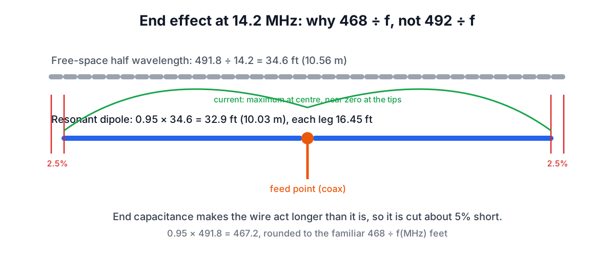
A dipole resonates when the current is zero at the tips and maximum at the feed point, with a standing wave of exactly half a wavelength between the ends. In a real wire the current does not quite reach zero at the physical end: the ends have capacitance to the surroundings, which behaves as if the wire continued a little further. The antenna therefore looks electrically longer than it is, and resonates lower than the free-space calculation predicts.
The correction is the end-effect factor K. For thin HF wire, a length about 5% short of a free-space half wave resonates at the target:
Half-wave free space: 983.57 ÷ 2 = 491.8 ÷ f feet With K = 0.95: 0.95 × 491.8 = 467.2 ÷ f feet
Round 467.2 to 468 and you have the textbook formula. The metric equivalent is about 142.6 ÷ f metres. The rounding makes 468/f about 0.2% longer than K = 0.95 exactly, which is harmless because you are going to trim anyway.
K is not a constant of nature. It depends on the ratio of the element's length to its diameter: a thin wire many thousands of diameters long sits near 0.97 to 0.98 by theory, while fat tubing at VHF, only a few hundred diameters long, drops toward 0.93 to 0.95. Insulated wire is slower still, because the plastic adds a little dielectric loading, so insulated dipoles typically end up 2 to 3% shorter than bare ones. Height above ground and nearby objects shift resonance too. 0.95 works as a starting figure because it errs long for typical HF wire, and long is the right direction to err.
The family of formulas
The same reasoning gives the other common types. All are in feet with f in MHz:
| Antenna | Fraction of λ | Rule of thumb | 14.2 MHz | 146 MHz |
|---|---|---|---|---|
| Half-wave dipole (total) | 0.5 × K | 468 ÷ f | 32.9 ft | 3.21 ft |
| Each dipole leg | 0.25 × K | 234 ÷ f | 16.5 ft | 19.2 in |
| Quarter-wave vertical | 0.25 × K | 234 ÷ f | 16.5 ft | 19.2 in |
| 5/8-wave vertical | 0.625 × K | about 585 ÷ f | 41.1 ft | 4.0 ft |
| Full-wave loop (perimeter) | about 1.02 | 1005 ÷ f | 70.7 ft | 6.9 ft |
The quarter-wave vertical is half a dipole with the ground plane (or radials) supplying the missing half as an image, so it uses the same 234 ÷ f as one dipole leg. The 5/8-wave vertical is popular on VHF mobiles because it concentrates radiation at low angles, but its feed impedance is not 50 Ω, so it needs a matching coil at the base; the length above is the radiator only.
The loop is the odd one: it is longer than a wavelength. A closed loop has no ends, so there is no end-effect shortening, and the loading of a loop shape makes it resonate at roughly 1.02 λ. The ARRL Antenna Book gives 1005 ÷ f feet, which the calculator uses.
Worked example: a 40 m dipole
Target 7.15 MHz, bare copper wire, flat-top at 10 m height.
- λ = 299.79 ÷ 7.15 = 41.93 m.
- Half wave = 20.96 m (68.8 ft).
- With K = 0.95: 19.92 m (65 ft 4 in) total, 9.96 m per leg. The rule 468 ÷ 7.15 gives 65.45 ft.
- Cut each leg about 2% long, roughly 10.15 m, plus enough extra to wrap round the insulators.
Now trim. Raise the antenna to its final height, measure SWR across the band, and find the frequency of minimum SWR. If the minimum is at 6.95 MHz, the antenna is about 3% too long (7.15 ÷ 6.95 = 1.029). Shorten each leg by 3%, which is about 30 cm, and measure again. Trim both legs equally to keep the feed point centred.
Inverted V, end-fed and other variations
An inverted V, a dipole with its centre high and ends sloping down, usually resonates lower than a flat dipole of the same wire length because the ends are closer to the ground, and is often cut 3 to 5% shorter. An end-fed half-wave uses the same total length as a dipole but needs a high-ratio transformer (often 49:1 or 64:1) at the feed point, because the impedance at the end of a half-wave wire is thousands of ohms. Trap and fan dipoles cover several bands with one feedline; each element is still cut from the same formula and then tuned in place, because elements interact.
Velocity factor and feedline sections
Inside a transmission line a wave travels slower than in air, because the electric field passes through the insulation. The ratio is the velocity factor, VF. A length of coax that is a quarter wave electrically is therefore physically shorter:
Physical length = VF × λ × fraction
| Line | Typical VF |
|---|---|
| Solid polyethylene coax (RG-58, RG-213) | 0.66 |
| Foam polyethylene coax (RG-8X) | about 0.78 |
| Low-loss foam (LMR-400) | 0.85 |
| 300 Ω TV twin-lead | about 0.80 |
| 450 Ω window line | about 0.91 |
| Open-wire ladder line | about 0.97 |
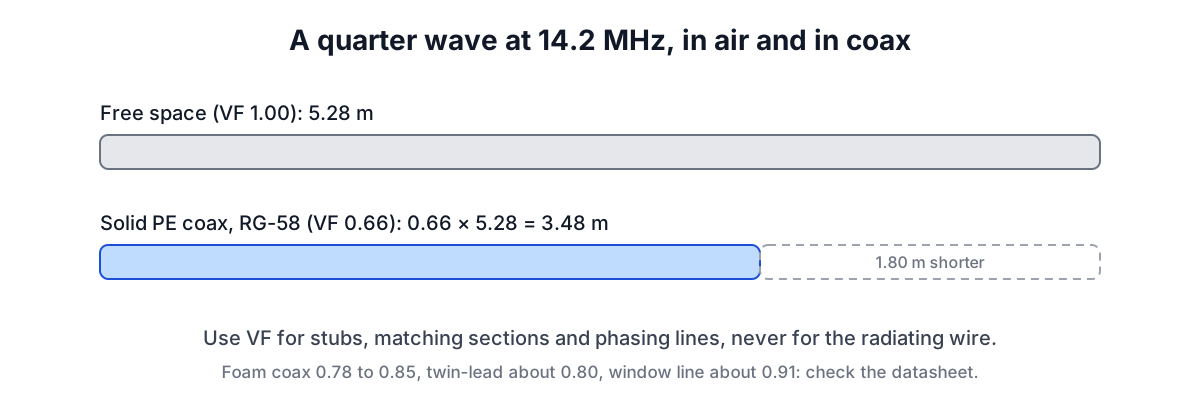
At 14.2 MHz a free-space quarter wave is 5.28 m, but a quarter-wave stub of RG-58 is 0.66 × 5.28 = 3.48 m. You need this for quarter-wave matching transformers, coax stubs used as filters or traps, phasing lines between stacked antennas, and the matching section of a J-pole built from twin-lead.
Velocity factor does not apply to the radiating wire of a dipole; that is what the end-effect factor covers. Do not multiply a dipole length by 0.66 because it is fed with coax. The feedline to a dipole can be any length; its velocity factor only matters if you are deliberately using a specific electrical length.
Velocity factor also varies between makers of nominally similar cable, especially foam types. Use the datasheet figure, or measure a stub with an antenna analyser: a quarter-wave open stub shows a low impedance at its resonant frequency.
Common mistakes
- Cutting to the exact formula length. Always cut long; you can trim but not add.
- Trimming one leg only. Trim both legs equally to keep the dipole balanced.
- Measuring SWR at ground level. Resonance moves as you raise the antenna; adjust it at working height.
- Applying coax velocity factor to the antenna. VF is for transmission lines; the wire uses K.
- Expecting VHF rods to match HF wire. Thick elements have a lower K; start a few percent shorter and tune.
Sources
- The ARRL Antenna Book, chapters on dipoles, loops and transmission lines (468 ÷ f, 234 ÷ f and 1005 ÷ f).
- The ARRL Handbook for Radio Communications, transmission line velocity factors.
- Cable makers' datasheets, for example Times Microwave LMR-400 (VF 0.85).
Related tools: the Reactance and Impedance Calculator for matching networks and the Decibel Calculator for feedline loss and gain.
Related searches
- dipole length formula
- 468 divided by frequency
- quarter wave vertical length
- 5/8 wave antenna length
- antenna end effect
- coax velocity factor
- full wave loop 1005
- how to trim a dipole
- 40 meter dipole length