
Ohm's Law, Resistor Color Codes and Voltage Drop Explained
How voltage, current, resistance and power relate, how to read 4, 5 and 6-band resistors and pick E-series values, and how to size cable for 3% voltage drop.
· 9 min read

Three questions come up again and again at a workbench or on a job site. How much current will flow, and how hot will this resistor get? What value is this little striped part? And why is the voltage at the far end of a long cable lower than at the panel? They look like separate topics, but all three are Ohm's law applied in different places. This guide works through each one with numbers you can reproduce in the Ohm's Law Calculator, the Resistor Color Code Calculator and the Voltage Drop Calculator. It explains the arithmetic and the reasoning behind common rules of thumb; it is not a substitute for your local electrical code or a qualified electrician.
Ohm's law and the power law
Georg Ohm showed in 1827 that, for a conductor at a steady temperature, current is proportional to voltage: I = V / R. Voltage is the push, resistance is the opposition and current is the flow. Double the voltage across a fixed resistor and the current doubles. Double the resistance and it halves.
Power adds the second relation, P = V × I. Substitute Ohm's law into it and you get P = I² × R and P = V² / R. With four quantities and two equations, any two known values give the other two, which is where the twelve-formula "Ohm's law wheel" comes from: three ways to get each of V, I, R and P.
Two worked cases show why both laws matter:
- A resistor on a 12 V rail. 12 V across 470 Ω drives 12 / 470 = 25.5 mA, and dissipates 12² / 470 = 0.306 W. A common quarter-watt resistor would be over its rating, so the right part is at least a half-watt, and better a one-watt part. Choosing a power rating of at least twice the expected dissipation keeps the part cool and long-lived.
- An LED. A 5 V supply, a red LED that drops about 2 V and a target of 20 mA leaves 3 V across the resistor, so R = 3 / 0.02 = 150 Ω and P = 3 × 0.02 = 60 mW. The mistake to avoid is using the whole 5 V: LEDs are not ohmic, so you apply Ohm's law to the resistor, not to the diode.
That second point is the main limit of Ohm's law. It describes resistors, wire and heating elements well. Diodes, transistors and lamps change their effective resistance with voltage or temperature. A tungsten filament can have a tenth of its hot resistance when cold, which is why bulbs usually fail at switch-on.
Reading resistor colour codes
Through-hole resistors are too small to print on, so the value is painted as bands. The digits run through the spectrum: black 0, brown 1, red 2, orange 3, yellow 4, green 5, blue 6, violet 7, grey 8, white 9. The multiplier band uses the same colours as powers of ten, plus gold for ×0.1, silver for ×0.01 and, since IEC 60062:2016, pink for ×0.001.
- Four bands: digit, digit, multiplier, tolerance. Yellow, violet, red, gold is 47 × 100 = 4,700 Ω at ±5%, so a good part measures between 4,465 and 4,935 Ω.
- Five bands: three digits, multiplier, tolerance. Brown, black, black, red, brown is 100 × 100 = 10 kΩ at ±1%.
- Six bands: as five bands, plus a temperature coefficient. Red, red, black, brown, brown, brown is 2.2 kΩ ±1% at 100 ppm/K, so it shifts by about 0.22 Ω per degree.
Tolerance colours are brown ±1%, red ±2%, green ±0.5%, blue ±0.25%, violet ±0.1%, gold ±5% and silver ±10%, with no band meaning ±20%. Read from the end where the bands are bunched; gold and silver never start a code.
Resistors are stocked in the IEC 60063 preferred values rather than round numbers. The E12 series (10, 12, 15, 18, 22, 27, 33, 39, 47, 56, 68, 82) suits ±10% parts, E24 adds values in between for ±5%, and E96 has 96 steps per decade for ±1%. Each step is the same ratio, about 21% for E12 and 2.4% for E96, so the series cover the decade evenly in percentage terms. If your calculation says 5 kΩ, the nearest E12 part is 4.7 kΩ (6% low), the nearest E24 is 5.1 kΩ (2% high) and the nearest E96 is 4.99 kΩ (0.2% low). The colour code calculator lists all three so you can pick based on how much the error matters.
Voltage drop: Ohm's law along a cable
Wire is a resistor too. Copper is an excellent conductor, but a long run of thin wire carrying a large current loses a noticeable share of the supply. The lost voltage is simply I × R for the cable, counted on every conductor the current passes through.
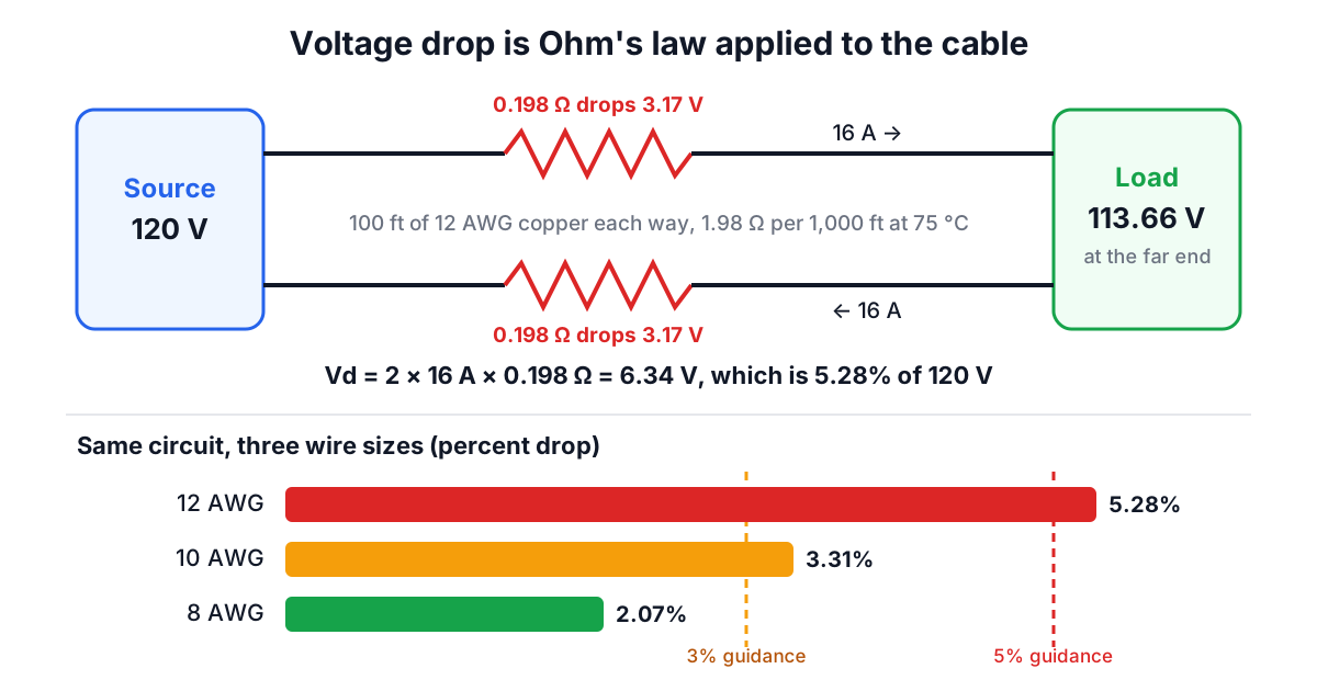
In a DC or single-phase circuit the current goes out on one conductor and back on the other, so the formula is Vd = 2 × I × R × L, with R per unit length and L the one-way distance. In a balanced three-phase circuit the return currents largely cancel, and the line-to-line drop is Vd = √3 × I × R × L.
Take the circuit in the diagram: 100 feet of 12 AWG copper from a panel to a 16 A load at 120 V. NEC Chapter 9 Table 8 gives stranded 12 AWG copper as 1.98 Ω per 1,000 feet at 75 °C, so each 100-foot conductor is 0.198 Ω. The drop is 2 × 16 × 0.198 = 6.34 V, or 5.28% of 120 V, leaving 113.66 V at the load. Going up to 10 AWG gives 3.3%; 8 AWG gives 2.07%.
Metric cable works the same way with IEC 60228 values, which are stated at 20 °C per kilometre. 2.5 mm² copper is 7.41 Ω/km cold. At a working temperature of 70 °C that rises to about 8.87 Ω/km, so a 20 m socket circuit carrying 16 A at 230 V loses about 5.7 V, or 2.5%.
Why temperature matters
Copper's resistance rises about 0.39% per degree Celsius from 20 °C, and aluminium's about 0.40%. A cable running at its rated current is warm, which is why NEC tables quote 75 °C. Setting the conductor temperature to 20 °C in the calculator gives a smaller, optimistic drop; setting it to the insulation rating gives a conservative one. For a quick check at full load, 75 °C (NEC) or 70 °C (PVC cable) is the sensible choice.
Copper versus aluminium
Aluminium conducts about 61% as well as copper, so the same size has roughly 1.6 times the resistance. A 250-foot, 100 A three-phase feeder at 480 V in 1/0 copper drops 5.28 V (1.10%); in 1/0 aluminium it drops 8.70 V (1.81%). Aluminium is lighter and cheaper per ampere, so it is common for large feeders, but it is upsized by about two AWG sizes to match.
How much drop is acceptable?
The figures most people quote come from informational notes in the US National Electrical Code: about 3% on a branch circuit or a feeder and 5% in total from the service to the farthest outlet. They are advice for reasonable efficiency and performance rather than enforceable requirements in most US jurisdictions. In the UK, BS 7671 sets 3% for lighting circuits and 5% for other uses on a public supply.
Low-voltage systems are where voltage drop bites hardest. 15 A over 20 feet of 10 AWG is a 0.74 V drop. On a 120 V circuit that is 0.6%; on a 12 V battery system it is 6.2%, enough to make inverters cut out and pumps run slowly. That is why RV, marine and solar wiring is often heavier than household wiring for the same current, and why higher system voltages (24 V, 48 V) are popular for larger off-grid installations: the same power at four times the voltage needs a quarter of the current, which cuts the drop by a factor of four and the cable loss by sixteen.
Two final judgment calls:
- Voltage drop and ampacity are separate checks. A cable must be big enough to carry the current safely (ampacity, set by insulation temperature, installation method and grouping), and big enough to keep the drop reasonable. On long runs, voltage drop usually decides; on short runs, ampacity does.
- Use the real load for the real drop, and the breaker size for the worst case. Motors also draw several times their running current at start-up, so the starting dip is much larger than the steady-state number.
Putting it together
A typical small project uses all three tools in sequence. Ohm's law gives the resistor value and power rating; the colour code calculator turns that value into the nearest stocked part and the bands to look for in the drawer; and the voltage drop calculator checks that the supply wiring delivers the voltage the circuit was designed for. The physics is the same throughout: voltage, current and resistance, applied to a different piece of copper each time.