
ISO 286 Fits and Tolerances: Reading H7/g6 and Choosing a Fit
IT grades, fundamental deviations, hole-basis versus shaft-basis, clearance, transition and interference fits, the Δ rule for K to P holes, and worked limits at 25 and 50 mm.
· 11 min read
A drawing that says "Ø25 H7" tells a machinist far more than a bare 25 mm, and "Ø25 H7/g6" on an assembly tells the designer how two parts will behave together. These short codes come from ISO 286, the international system of limits and fits. This guide explains how the codes are built, how to turn them into sizes, how the three kinds of fit differ, and how to choose one. The ISO Fits and Tolerances Calculator gives the limits for any size up to 500 mm.
Two ideas: zone width and zone position
Every tolerance class has two parts.
The number is the IT grade (international tolerance grade). It sets how wide the tolerance zone is. Grades run from IT01 and IT0 (gauge blocks) through IT1 to IT18 (rough work). The width grows with size, because a large part is harder to hold to the same micrometres. ISO 286-1 tabulates it for size ranges:
| Size range (mm) | IT5 | IT6 | IT7 | IT8 | IT9 | IT11 |
|---|---|---|---|---|---|---|
| over 10 to 18 | 8 | 11 | 18 | 27 | 43 | 110 |
| over 18 to 30 | 9 | 13 | 21 | 33 | 52 | 130 |
| over 30 to 50 | 11 | 16 | 25 | 39 | 62 | 160 |
| over 50 to 80 | 13 | 19 | 30 | 46 | 74 | 190 |
| over 80 to 120 | 15 | 22 | 35 | 54 | 87 | 220 |
Values in micrometres. Each grade from IT6 upward is about 1.6 times the one before, a geometric progression.
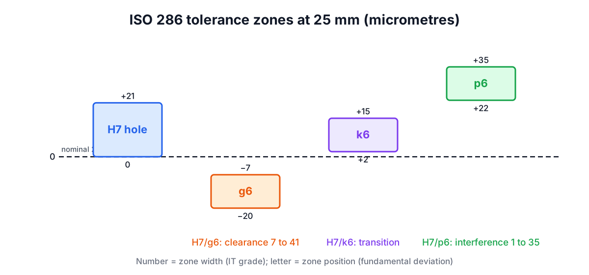
The letter is the fundamental deviation. It sets where the zone sits relative to the nominal size. Upper-case letters are holes, lower-case letters are shafts. H and h start exactly at the nominal size: an H hole is never smaller than nominal and an h shaft is never larger. Letters earlier in the alphabet move the zone away from the material (looser), later letters move it into the material (tighter).
Turning a class into sizes
The fundamental deviation gives one edge of the zone and the IT grade gives the other.
25 H7: H has a lower deviation of 0. IT7 at 25 mm is 21 µm. So the hole is +0 / +21 µm: 25.000 to 25.021 mm.
25 g6: g has an upper deviation of −7 µm at this size. IT6 is 13 µm. So the shaft is −7 / −20 µm: 24.980 to 24.993 mm.
25 p6: p has a lower deviation of +22 µm. Adding IT6 gives +22 / +35 µm: 25.022 to 25.035 mm.
The fundamental deviations for shafts are tabulated in ISO 286-1 by size range. A few rows:
| Range (mm) | f (es) | g (es) | k (ei) | m (ei) | n (ei) | p (ei) |
|---|---|---|---|---|---|---|
| over 18 to 30 | −20 | −7 | +2 | +8 | +15 | +22 |
| over 30 to 50 | −25 | −9 | +2 | +9 | +17 | +26 |
| over 50 to 80 | −30 | −10 | +2 | +11 | +20 | +32 |
"es" is the upper deviation of a shaft, "ei" the lower. The r and s shafts split some ranges further above 50 mm: s is +53 µm from 50 to 65 mm but +59 µm from 65 to 80 mm, for example.
The three kinds of fit
Pair a hole with a shaft of the same nominal size and compute two numbers:
- Maximum clearance = largest hole − smallest shaft = hole upper deviation − shaft lower deviation.
- Minimum clearance = smallest hole − largest shaft = hole lower deviation − shaft upper deviation.
A negative clearance is interference.
| Result | Fit type | What it means |
|---|---|---|
| Minimum clearance ≥ 0 | Clearance | Parts always go together freely |
| Maximum clearance ≤ 0 | Interference | Parts must be pressed, shrunk or expanded together |
| In between | Transition | Depends on the actual parts: slight clearance or slight interference |
Worked through at 25 mm with an H7 hole:
- H7/g6: max 21 − (−20) = 41 µm, min 0 − (−7) = 7 µm. Clearance fit.
- H7/h6: max 34 µm, min 0. Clearance, but the tightest pair just touches.
- H7/k6: max 21 − 2 = 19 µm, min 0 − 15 = −15 µm. Transition.
- H7/p6: max 21 − 22 = −1 µm, min 0 − 35 = −35 µm. Interference every time.
Hole basis or shaft basis
In the hole-basis system every hole is H and the fit is set by choosing the shaft letter. This is the default in most industries, because holes are made with fixed-size tools (drills, reamers, boring heads set to size) and checked with fixed-size plug gauges. Standardising on H7 means one reamer and one gauge for many fits.
In the shaft-basis system every shaft is h and the fit is set by the hole letter. It suits designs where a single precision shaft, often ground bar stock to h6 or h7, passes through several parts with different fits, such as a line shaft carrying a pulley, a bearing and a coupling.
The two systems are designed to give the same clearances: G7/h6 behaves like H7/g6. For holes K, M, N and P at finer grades, that equivalence needs a correction. ISO 286-1 adds Δ = ITn − IT(n−1) to the hole deviation. K7 at 25 mm is therefore not the mirror of k7 (−2 µm); it is −2 + (21 − 13) = +6 µm upper and −15 µm lower. The calculator applies the Δ rule, and the one documented exception: M6 between 250 and 315 mm has an upper deviation of −9 µm rather than the −11 µm the rule would give.
Choosing a fit
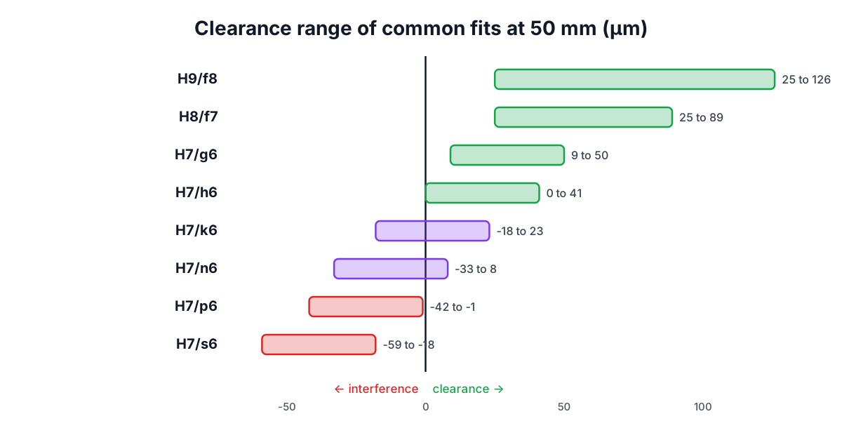
The table below gives widely used hole-basis fits with typical applications. Treat them as starting points; the right choice depends on loads, materials, temperature and assembly method.
| Fit | Type | Typical use |
|---|---|---|
| H11/c11 | Loose running | Agricultural and construction pins, wide tolerances |
| H9/f8 | Loose running | Plain bearings with temperature swings |
| H8/f7 | Close running | Machine spindles, gearbox shafts in bushes |
| H7/g6 | Sliding | Locating spigots, sliding gears, pistons in guides |
| H7/h6 | Locational clearance | Stationary parts assembled by hand |
| H7/k6 | Locational transition | Gears, pulleys and couplings on keyed shafts |
| H7/n6 | Tight transition | More accurate location, light press |
| H7/p6 | Locational interference | Rigid location without heavy hub stress |
| H7/s6 | Medium drive | Permanent press or shrink fits on steel hubs |
The calculator covers the letters from f to s for shafts and F to P for holes; the very loose classes such as c are left out.
Some rules of thumb:
- Use the coarsest grade that does the job. Going from IT7 to IT6 on a shaft usually means grinding instead of turning.
- Holes are given one grade coarser than shafts (H7 with a 6-grade shaft), because holes are harder to make accurately.
- For interference fits, the interference is only half the story. The resulting pressure, hub stress and press force need a thick-walled cylinder (Lamé) calculation with the real materials and wall thicknesses.
- Rolling bearings have their own tolerance standard (ISO 492) and the maker's tables for shaft and housing fits; use those rather than a generic fit.
Size ranges and edge cases
ISO 286 assigns the same deviations to every size within a range, and ranges are "over" the lower value "up to and including" the upper. So 30.0 mm uses the 18 to 30 mm row and 30.01 mm uses the 30 to 50 mm row. A shaft of nominal 30 mm in g6 is −7/−20 µm; at 30.5 mm it becomes −9/−25 µm.
The js and JS classes are symmetrical: ±IT/2. At 25 mm, js6 is ±6.5 µm.
Imperial work
ISO 286 is metric, but the limits convert directly: 1 thou (0.001 in) is 25.4 µm. A 1 in nominal (25.4 mm) H7/g6 gives 7 to 41 µm, or roughly 0.3 to 1.6 thou of clearance. North American drawings often use ANSI B4.1 classes instead (RC, LC, LT, LN, FN), which are defined in inches but cover similar ground.
Temperature and finish
Fits are specified at 20 °C (ISO 1). A steel shaft in an aluminium housing gains clearance as the assembly warms, because aluminium expands about twice as much as steel: a 50 mm bore heated by 50 °C grows by roughly 58 µm against the shaft's 29 µm. The Thermal Expansion Calculator gives the numbers. Surface roughness also matters: the peaks of a turned surface flatten on assembly, so a fit with only a few micrometres of clearance or interference needs a fine finish to behave as drawn.
Sources
- ISO 286-1:2010, Geometrical product specifications (GPS), ISO code system for tolerances on linear sizes, Part 1: Basis of tolerances, deviations and fits.
- ISO 286-2:2010, Part 2: Tables of standard tolerance classes and limit deviations for holes and shafts.
- ISO 1, standard reference temperature for geometrical product specification (20 °C).
Related reading: Bolt Circle Coordinates for laying out holes, and the Bearing Life Calculator for the bearings those fits often hold.
Related searches
- iso 286 fits
- h7 g6 fit
- h7 p6 interference
- it grade table
- hole basis system
- transition fit h7 k6
- fundamental deviation
- shaft tolerance table
- press fit tolerance