
Belt Length and Pulley Speed Formulas, Derived and Checked
The exact open-belt length formula from tangent geometry, where the handbook approximation comes from and when it drifts, wrap angle and slip, and how to go from a stock belt back to centre distance.
· 9 min read

A two-pulley belt drive looks like the simplest machine in the workshop, and the speed part of it is. The geometry part, how long the belt must be and where the motor has to sit, is where people reach for a formula, copy it from somewhere, and occasionally end up with a belt that will not go on. This post derives the exact open-belt length from tangent geometry, shows how the shorter handbook formula falls out of it and when it drifts, and covers the two numbers that decide whether a friction belt actually drives: wrap angle and belt speed. Every figure can be reproduced in the Pulley and Belt Calculator.
Pulley speeds: one belt, one speed
A belt that does not slip moves at the same linear speed over both pulleys. A point on the pitch circle of a pulley of diameter D turning at n rpm travels π x D x n per minute, so
D1 x n1 = D2 x n2
Any one of the four values follows from the other three. A 100 mm motor pulley at 1,750 rpm driving a 250 mm pulley turns it at 1,750 x 100 / 250 = 700 rpm, a 2.5 : 1 reduction. Belt speed is the same product in consistent units:
v = π x D1 x n1 / 60     (m/s with D in metres)
  = π x 0.100 x 1,750 / 60 = 9.16 m/s  (1,804 ft/min)
Two corrections apply in practice. First, the diameter that matters is the pitch diameter, measured at the belt's neutral layer. For a V-belt that sits a little inside the outer rim of the sheave; for a timing belt it is outside the tooth tips. Belt catalogues list pitch diameters for every pulley, and using the rim diameter instead introduces a small ratio error and a larger length error. Second, friction belts creep: the belt stretches more on the tight side than the slack side, so the driven pulley runs about 1 to 3% slower than the ideal ratio. The calculator has a slip field for that. Timing belts and chains have no creep.
Deriving the exact belt length
For an open belt (not crossed) the straight spans leave each pulley at a tangent. Draw the line of centres, length C, between a large pulley of diameter D and a small one of diameter d. Each straight span is offset from the line of centres by an angle
φ = asin( (D - d) / (2C) )
because the difference in radii, (D − d)/2, is the side opposite φ in a right triangle whose hypotenuse is C.
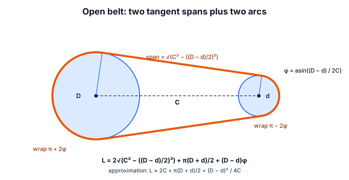
Each straight span has length √(C² − ((D − d)/2)²) by Pythagoras. The belt wraps the large pulley through π + 2φ radians and the small pulley through π − 2φ. Adding the two spans and the two arcs:
L = 2√(C² - ((D - d)/2)²) + (D/2)(π + 2φ) + (d/2)(π - 2φ)
  = 2√(C² - ((D - d)/2)²) + π(D + d)/2 + (D - d)φ
This is exact for an ideal thin belt, and it is the form given in Shigley's Mechanical Engineering Design (Table 17-2). For the 100 and 250 mm pulleys at 500 mm centres it gives 1,561.05 mm.
Where the handbook approximation comes from
The approximation printed in Machinery's Handbook and many belt catalogues is
L ≈ 2C + π(D + d)/2 + (D - d)² / (4C)
It comes from expanding the exact formula for small φ. The square root is about C − (D − d)²/(8C), and (D − d)φ is about (D − d)²/(2C). Doubling the first and adding the second gives 2C + (D − d)²/(4C). The terms dropped are of order (D − d)⁴/C³, which is tiny when the diameter difference is small compared with the centre distance.
How small is tiny? For the default drive, the approximation gives 1,561.03 mm, 0.02 mm short of exact. Push the geometry: 80 and 400 mm pulleys at only 300 mm centres. Exact length 1,441.5 mm, approximation 1,439.3 mm, a 2.2 mm gap. That is still within the adjustment range of most drives, but on a short-centre timing belt drive with little take-up it can decide whether a stock belt fits. The calculator shows both side by side so you can see the difference for your layout.
From a stock belt back to centre distance
Belts come in stock lengths, so the usual workflow runs backwards: pick the nearest available belt, then find where the motor goes. The approximation can be rearranged into a quadratic in C. Multiplying through by 4C:
8C² - (4L - 2π(D + d))C + (D - d)² = 0
C = [ b + √(b² - 32(D - d)²) ] / 16,     b = 4L - 2π(D + d)
For the default pulleys and a 1,600 mm belt this gives 519.70 mm. The exact formula has no closed-form inverse, but belt length rises steadily with C (the derivative works out to 2√(C² − a²)/C, which is always positive), so a simple bisection solves it to any precision. The calculator does this and returns 519.69 mm. Allow travel either side: inward to slip the belt over the flanges without prying, outward for tensioning and for belt stretch in service.
Wrap angle, slip and belt speed
The small pulley's wrap angle is
θ = 180° - 2 asin( (D - d) / (2C) )
For the default drive that is 162.7 degrees. It matters because a friction belt transmits force through friction over the arc of contact, and the capstan (Euler-Eytelwein) relation says the ratio of tight-side to slack-side tension is limited to e^(μθ). Less wrap means a smaller ratio, so less torque before the belt slips. V-belt makers apply an arc-of-contact correction factor that falls below 1 as wrap drops from 180 degrees, reaching around 0.8 or so at 120 degrees. Below about 120 degrees, use longer centres, a smaller ratio per stage or a backside idler to add contact. The 80/400 mm example above has only 115.5 degrees and would struggle.
Belt speed sets power capacity and life. Power is tension difference times speed, so faster belts carry more power at the same tension, but centrifugal force also rises with v² and eats into the useful tension. Classical V-belts typically perform best around 20 to 25 m/s (about 4,000 to 5,000 ft/min), and standard cast iron sheaves are usually limited to about 30 to 33 m/s rim speed. The calculator flags anything above 30 m/s. Belt passes per minute (belt speed divided by belt length) is a useful life indicator too: very short, fast belts flex more often and run hotter.
Common mistakes
- Using outside diameter for a V-belt sheave. It inflates the length and slightly shifts the ratio. Use the catalogue pitch diameter.
- Forgetting the belt crosses itself. A crossed belt reverses the driven pulley's direction and is longer: the formula uses (D + d) in place of (D − d) and gives 1,611.7 mm for the default drive instead of 1,561.0. Crossed belts are rare outside flat-belt drives.
- Centres too short. A common rule is centre distance at least the larger pulley diameter and no more than about three times the sum of the diameters. Below the lower limit, wrap suffers; above the upper, long spans flap.
- No allowance for take-up. A drive designed to the exact belt length with a fixed motor cannot be tensioned or re-tensioned.
When the simple model is not enough
The formulas here are geometry and kinematics. Selecting the belt section and the number of belts uses the manufacturer's power ratings per belt at the small pulley's speed and diameter, corrected for arc of contact and belt length, multiplied by a service factor for the driven machine (higher for crushers than for fans). Bearing and shaft loads come from the belt tension, which for V-belts is typically set by a deflection-force check. Very large speed ratios or very short centres move outside the assumptions and need the belt maker's design software.
For the shaft torque on each pulley, use the Torque and Power Calculator; for geared alternatives, the Gear Ratio Calculator and the companion post on gear train ratios. Shaft bearings can be checked with the Bearing Life Calculator. The calculator results are for preliminary layout. Guard every belt drive, and have safety-critical drives checked by a qualified engineer against the belt maker's ratings.