
Gear Train Ratios Explained: Simple, Compound, Idlers and Losses
Why tooth counts set the speed ratio, why compound ratios multiply and idlers cancel, how torque and efficiency carry through a train, and the tooth-count rules that keep gears quiet and long-lived.
· 9 min read

A gear train is a lookup table for speed and torque written in teeth. Count the teeth on each gear and you know, to the last decimal place, how fast every shaft turns relative to the input, because teeth cannot slip. What the tooth counts do not tell you is how much torque survives the friction in each mesh, which way the output turns, and whether the gears will be quiet and last. This post covers all four, with numbers you can reproduce in the Gear Ratio Calculator.
Why tooth counts set the ratio
Two gears in mesh share a pitch point where their pitch circles touch and roll without sliding. At that point both have the same linear speed, so
π x d1 x n1 = π x d2 x n2
where d is the pitch diameter and n the speed. Gears that mesh must have the same tooth size (module in metric, diametral pitch in inch units), and pitch diameter is module times tooth count, so the module cancels and the relation becomes
N1 x n1 = N2 x n2 → n1 / n2 = N2 / N1
The speed ratio of a single mesh is the driven tooth count divided by the driver tooth count. A 12-tooth pinion driving a 36-tooth gear gives 36 / 12 = 3: the output turns at a third of the input speed. This calculator, like most gearbox catalogues, reports the ratio as input speed over output speed, so a reduction is a number above 1 (3 : 1) and an overdrive is below 1 (1 : 2 when the output turns twice as fast).
Compound trains multiply, idlers cancel
Put a second gear on the shaft of the 36-tooth gear and you have a compound train. Gears on one shaft turn together, so the second stage starts at the first stage's output speed and divides it again. The ratios multiply:
i = (N2 / N1) x (N4 / N3) x ... = product of driven teeth / product of driver teeth
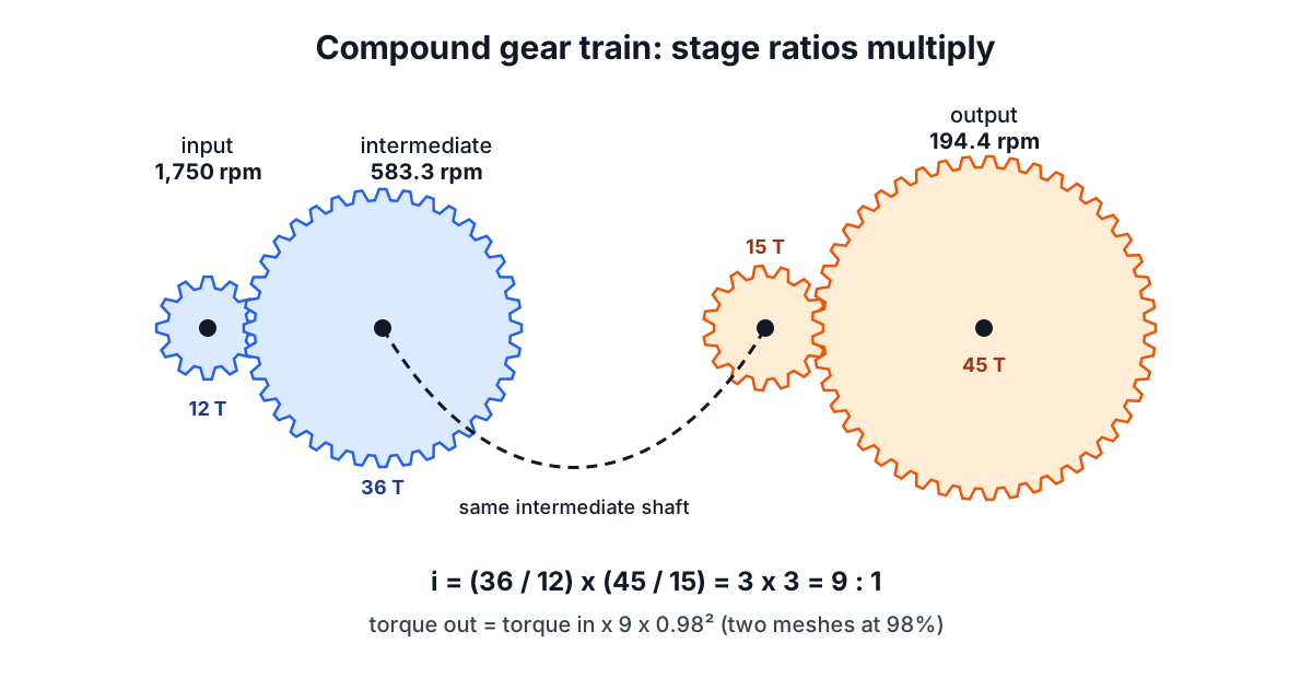
With 12 → 36 then 15 → 45 the overall ratio is 3 x 3 = 9. A 1,750 rpm motor gives 583.3 rpm on the intermediate shaft and 194.4 rpm at the output. A single 9 : 1 pair would need, for example, a 12-tooth pinion and a 108-tooth gear, a much larger wheel than the two-stage version. Spur gear stages above about 6 : 1 are rarely economic for that reason.
An idler is a gear placed between driver and driven on its own shaft. It is the driven gear of the first mesh and the driver of the second, so its tooth count appears once on top and once on the bottom and cancels. A 20-tooth gear driving a 60-tooth gear through a 37-tooth idler is still 3 : 1. Idlers are used to bridge a distance between shafts or to change direction, and they cost an extra mesh of friction.
Direction of rotation
Two external gears in mesh turn in opposite directions. Each external mesh is one reversal, so
- one mesh: output opposite to input
- two meshes (a compound train, or a pair with one idler): same direction
- three meshes: opposite again
An internal (ring) gear is the exception. A pinion inside a ring turns the same way as the ring, so that mesh does not reverse. The calculator counts reversals stage by stage and reports the result. Planetary gearsets, where a carrier holding the planet gears also turns, need the Willis equation instead and are outside this simple chain model.
Torque, power and efficiency through the train
Power in a gear mesh is torque times speed, and a mesh loses only a small fraction of it. If speed is divided by i, torque is multiplied by i, less the losses:
T_out = T_in x i x η^m
where η is the efficiency per mesh and m the number of meshes. Precision-cut, well-lubricated spur and helical gears run at roughly 98 to 99% per mesh at rated load. Losses come from sliding friction along the tooth flank, oil churning and bearings. Because they multiply, a train's efficiency falls with every mesh: two meshes at 98% pass 96.04%, four pass 92.2%.
Worked through for the page default: 20 N·m in at 1,750 rpm through 12 → 36 and 15 → 45 at 98% per mesh,
lossless output torque  = 20 x 9          = 180.0 N·m
with losses             = 180 x 0.98²     = 172.9 N·m
input power             = 20 x 2π x 1,750 / 60 = 3.665 kW
power lost as heat      = 3.665 x (1 - 0.9604) = 0.145 kW
That 145 W has to leave the gearbox as heat, which is why larger reducers have thermal ratings as well as torque ratings. The intermediate shaft carries 58.8 N·m at 583 rpm; the output shaft carries 172.9 N·m. Shaft diameters, keys and bearings grow towards the output for that reason. The Torque and Power Calculator converts these torques between units, and the Bearing Life Calculator takes the shaft loads from here.
Worm gears are a different case. Their teeth slide rather than roll, and efficiency ranges from about 50% at high ratios to 90% at low ones, depending on lead angle and friction. Use the manufacturer's figure rather than a spur-gear default.
Choosing tooth counts
The ratio is only the start. Tooth counts also decide whether the gears can be cut, how quietly they run and how evenly they wear.
Minimum pinion teeth. For standard 20 degree full-depth involute teeth, a pinion with fewer than about 17 teeth is undercut by the cutter when meshing with a rack, which weakens the root. The limit is 2 / sin²(20°) = 17.1. Profile shift (addendum modification) allows fewer, which is common in compact gearboxes, but without it 17 or more is the safe default. Against a mating gear rather than a rack the limit is a little lower, down to about 13 teeth for a pair of equal gears, and it rises back towards 17 as the mating gear gets larger.
Hunting teeth. If the tooth counts share a common factor, the same pair of teeth meet every few revolutions and any defect wears a matched pattern. 12 and 36 share a factor of 12, so each pinion tooth meets only three gear teeth. Choosing 12 and 37 (ratio 3.083) makes every pinion tooth meet every gear tooth in turn and spreads wear. Where the exact ratio matters more, as in a clock or an indexing head, this rule gives way.
Exact ratios. Because tooth counts are integers, some ratios cannot be hit exactly in one stage. Compound trains give more combinations: 3.6 : 1 is 18 → 65 (3.611) in one stage, or exactly 3 x 1.2 with 20 → 60 and 25 → 30 in two.
Same module across a mesh. Only gears with the same module (or diametral pitch) and pressure angle can mesh. Centre distance then follows from module x (N1 + N2) / 2, so the tooth counts also set the shaft spacing.
When the simple model breaks down
The calculations here are kinematic plus a fixed efficiency. They do not check whether the teeth are strong enough. Gear rating standards, AGMA 2001 in the US and ISO 6336 internationally, check tooth bending stress at the root and surface contact (pitting) stress on the flank, with factors for dynamic load, misalignment, material and life. Output torque from this calculator is the input to that check, not a substitute for it.
Real efficiency also varies with load and speed: at light load the fixed churning losses are a larger share, and a reducer quoted at 97% at full load may be well below that at 20%. Backlash, the small clearance between teeth, does not change the ratio but matters for positioning systems that reverse direction.
For belt and chain alternatives to gears, see the Pulley and Belt Calculator and its companion post on belt length and pulley speed formulas. For machining the gears themselves, the Speeds and Feeds Calculator gives cutting parameters. For vehicle gearing with tyre sizes, the Gear Speed Calculator works from axle ratio and tyre diameter.
Results from the calculator are for preliminary design. Gearboxes in lifting equipment, vehicles or anything where failure could injure someone need a full rating to the applicable standard and a check by a qualified engineer.