
Bend Allowance, Bend Deduction and the K-Factor Explained
Where the neutral axis sits in a bend, how bend allowance, setback and bend deduction relate, how to measure your own K-factor from a test strip, and why tight air bends need a smaller K.
· 10 min read

Every flat pattern for a bent part rests on one physical fact: somewhere inside the thickness of the sheet there is a layer that neither stretches nor compresses as the sheet bends. The outside fibres get longer, the inside fibres get shorter, and this neutral layer keeps the length it had when the sheet was flat. If you know where it sits and how far it travels around the bend, you know how much material the bend consumes. This post works through the geometry behind bend allowance, outside setback and bend deduction, explains what the K-factor really is, and shows how to measure your own. All the numbers can be reproduced in the Bend Allowance Calculator.
The neutral axis and the K-factor
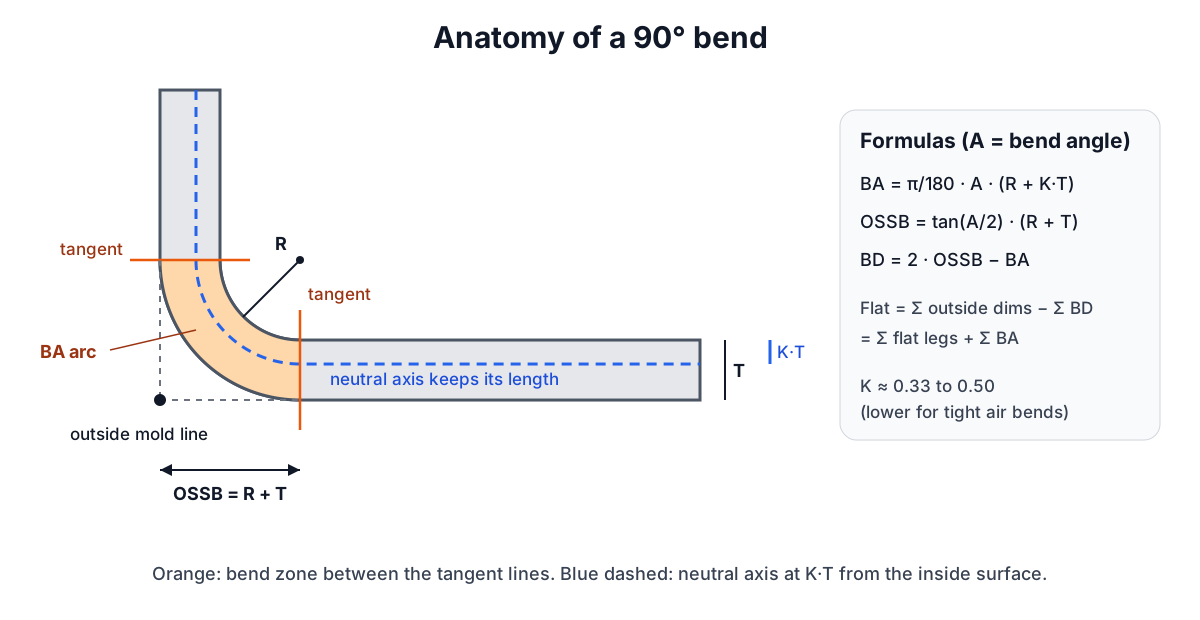
Picture a strip of sheet of thickness T bent around an inside radius R. The inside surface follows an arc of radius R, the outside surface an arc of radius R + T. The neutral axis follows an arc somewhere between, at radius R + t, where t is its distance from the inside surface. The K-factor is just that distance as a fraction of the thickness:
K = t / T
If the material behaved like a textbook beam, the neutral axis would stay in the middle and K would be 0.5. In practice, when the radius is tight compared with the thickness, the outside of the bend thins as it stretches and the inside thickens as it is squeezed, and the neutral layer shifts toward the inside. Practical K-factors therefore run from about 0.33 for very sharp air bends in soft material up to 0.5 for gentle bends where the radius is several times the thickness. The Fabricator’s analyses of measured bends put almost all real values between 0.33 and 0.5, and none above 0.5.
Bend allowance: the arc length of the neutral axis
Once K is known, the length of material inside the bend is the arc length of a circle of radius R + K x T swept through the bend angle A:
BA = (π / 180) x A x (R + K x T) A in degrees
That is the whole of bend allowance. It is measured between the two tangent lines, the lines across the part where the flat faces stop and the curved bend zone begins. To get a blank length from it, add the flat legs and the allowances:
flat length = Σ flat legs + Σ BA
Machinery’s Handbook gives an empirical version of the same thing, BA = A x (0.01743 R + 0.0078 T) with A in degrees. The first coefficient is π/180 rounded, and dividing the second by it gives K ≈ 0.447, which is why values near 0.44 to 0.45 turn up as default K-factors so often.
Setback and bend deduction: working from the drawing
Drawings rarely dimension flat legs. They dimension to mold lines, the points where the flat outside faces would meet if extended past the bend. The outside setback is the distance from each tangent line to that outside intersection:
OSSB = tan(A / 2) x (R + T)
For a 90° bend tan 45° = 1 and the setback is simply R + T. If you add up the outside dimensions of a part you have counted two setbacks for each bend but none of the bend allowance, so the correction per bend is the bend deduction:
BD = 2 x OSSB − BA
flat length = Σ outside dimensions − Σ BD
Some drawings dimension to the inside mold lines instead. The inside setback is tan(A/2) x R, and the correction per bend becomes 2 x ISSB − BA. All three routes, flat legs plus allowances, outside dimensions minus deductions and inside dimensions minus their correction, describe the same part and must give the same blank. The calculator lets you enter whichever your drawing uses; mixing styles within one drawing is the classic source of a part that is out by exactly one thickness.
A worked example
Take a U channel in 2 mm mild steel with an inside radius of 2 mm, air bent, outside dimensions 50 x 30 x 50 mm. With R/T = 1 the generic table gives K = 0.38 for a medium-hard material.
BA   = π/2 x (2 + 0.38 x 2)   = 4.335 mm
OSSB = tan 45° x (2 + 2)      = 4.000 mm
BD   = 2 x 4.000 − 4.335      = 3.665 mm
flat = 50 + 30 + 50 − 2 x 3.665 = 122.67 mm
Check by the flat-leg route: the legs between tangent lines are 50 − 4 = 46, 30 − 8 = 22 and 46 mm, which add to 114; adding two allowances of 4.335 gives the same 122.67 mm. If the K-factor were really 0.44, each allowance would grow by π/2 x 0.06 x 2 = 0.19 mm and the blank by 0.38 mm. Small, but on a part with eight bends and a tolerance of ±0.25 mm it is the difference between good and scrap.
Typical K-factors and where they come from
The table below is the generic chart reproduced in many fabrication handbooks and course notes. It groups materials into soft (aluminium, copper), medium (mild steel) and hard (stainless and spring steels), and the forming method into air bending, bottoming and coining:
| Method | Material | R ≤ T | T < R ≤ 3T | R > 3T |
|---|---|---|---|---|
| Air bending | soft / medium / hard | 0.33 / 0.38 / 0.40 | 0.40 / 0.43 / 0.45 | 0.50 |
| Bottoming | soft / medium / hard | 0.42 / 0.44 / 0.46 | 0.46 / 0.47 / 0.48 | 0.50 |
| Coining | soft / medium / hard | 0.38 / 0.41 / 0.44 | 0.44 / 0.46 / 0.47 | 0.50 |
Treat it as a starting point. The real K depends on the material lot, its yield strength, the grain direction, the die width and even the bend angle. Historic shop bend charts were often accurate only for the shop that made them, for exactly this reason.
Measuring your own K-factor
The reliable way to get K is to bend a test strip in the tooling you will use:
- Shear a strip of known length L, at least 50 mm wide, from the same sheet.
- Make one 90° bend near the middle and measure the two outside flange lengths, a and b, with the bend at exactly 90°.
- The bend deduction is BD = a + b − L.
- The bend allowance is BA = 2 x (R + T) − BD for a 90° bend.
- K = (BA / (π/2) − R) / T, using the inside radius you measured with a radius gauge.
Do this for each material, thickness and die combination you use often and keep the numbers in a small table by the brake. Enter the result as your own K in the calculator.
Bend angle versus included angle
A source of silent errors is the angle itself. The bend angle is how far the flange turns from flat: 90° for a right angle, 30° for a slight kink. The included angle is the angle between the two flanges after bending: 90° for a right angle, 150° for that slight kink. They add to 180°. All the formulas above take the bend angle. A drawing that calls out a 135° included angle needs A = 45° in the formulas, which gives an outside setback of tan 22.5° x (R + T), far smaller than the R + T of a right-angle bend. The calculator converts automatically when you choose the included-angle convention.
When the simple model breaks down
- Very tight radii. Below about R = 0.5 T the outside of the bend thins markedly and the material can crack; the K-factor model becomes unreliable.
- Sharp bends in a wide die. In air bending the inside radius is set by the die opening, roughly 16% of V in mild steel, not by the punch tip. Entering the punch radius gives a blank that is too long. The press brake tonnage calculator estimates the formed radius for your die.
- Hems and closed bends. Past about 120° the setback formula grows quickly and hems are better handled with dedicated hem allowances from a test piece.
- Springback. The angle you set on the brake is not the angle you get, but springback does not change the developed length much; it changes the angle, which you correct with ram depth.
Once the blank length is right, the sheet metal weight calculator turns it into a weight, and the gauge converter confirms the decimal thickness behind a gauge callout. For a deeper look at the brake side of the job, read press brake tonnage, V-die width and the air-bent radius.