
Press Brake Tonnage, V-Die Width and the Air-Bent Radius
Where the 575 x T² / V formula comes from, how material, die width and method change it, the 8 x T die rule, the 20% radius rule, minimum flange length and load limits.
· 10 min read
Every press brake job starts with three questions. Will the press bend it? What die should it go in? And what radius and minimum flange will that die give? They are linked: the die opening sets the force, the force sets which press and tooling you can use, and the same die opening sets the inside radius the part ends up with. This post explains the standard air-bending tonnage formula, where its constant comes from, how material and method change it, and the rules of thumb for die width, radius and flange length that go with it. The Press Brake Tonnage Calculator applies all of them at once.
How air bending works
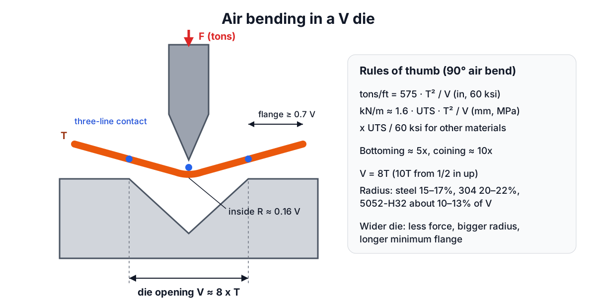
In air bending the sheet rests on the two shoulders of a V die and the punch pushes it down between them. The sheet only touches three lines: the punch tip and the two die shoulders. The bend angle is set by how far the punch descends, not by the shape of the tools, so one punch and die can make any angle from nearly flat down to the die angle. That flexibility is why most modern brake work is air bent.
Mechanically it is a three-point bending test. The load the press must apply is the load that makes the sheet yield fully across its thickness over the span of the die opening V.
The tonnage formula and where 575 comes from
The working formula in press brake and tooling charts, in inch units, is:
tons per foot = 575 x T² / V
with T the thickness and V the die opening in inches, for a 90° air bend in mild steel of 60,000 psi tensile strength. Bystronic and The Fabricator both state it with AISI 1035 cold-rolled steel as the baseline. Multiply by the bend length in feet for the total.
The shape of the formula follows from beam theory. The load to bend a plate over a span V is proportional to the plastic moment of the section, which scales with T² per unit length, divided by the lever arm, which scales with V. The constant 575 bundles together the material strength, the conversion to tons and an empirical factor for the real geometry, including the die radii and the fact that the sheet is not a simple beam at these proportions.
In metric units the same relation becomes about:
kN per metre ≈ 1.6 x UTS (MPa) x T² / V (T and V in mm)
Many European and Asian press makers publish a version written as 1.42 x UTS x T² / V with a 450 MPa baseline. The two forms agree within a few percent for mild steel. They are rules for 90° bends at roughly 8 x T die openings; the press maker’s chart for your tooling is the final word.
Material, die width and method
Material. Force scales with tensile strength, so other materials are handled with a factor of UTS / 60 ksi. Stainless 304 at around 85 ksi needs about 1.4 times the force of mild steel; 5052-H32 aluminium at 33 ksi about 0.55 times; high-strength steels with 100 ksi or more need well over 1.5 times. Use the mill certificate value where you have it, because tensile strength varies more between heats than people expect.
Die width. Tonnage is inversely proportional to V. Moving from an 8 x T die to a 10 x T die cuts the force by 20%. The price is a larger inside radius and a longer minimum flange.
Method. Bottoming presses the sheet against the die faces to set the angle more precisely; it needs around five times the air-bend force. Coining drives the punch tip into the sheet beyond the neutral axis, thinning it, and needs ten times or more. These multipliers are why coining is rare on modern CNC brakes and why bottoming thick plate is usually impractical.
The die opening rule
The usual starting point is a die opening of eight times the thickness for sheet up to about 1/2 in (12 mm) and ten times above that. It balances force, radius and flange length, and it is the ratio most published tonnage charts are built around. Openings between about 6 and 12 x T are workable:
- Below 6 x T the force climbs steeply, the shoulders mark the part, and the outside of the bend can crack in less ductile material.
- Above 12 x T the radius grows large, the angle becomes sensitive to small variations in thickness and strength, and springback increases.
The inside radius: the 20% rule
In air bending the punch tip only controls the radius when it is larger than the radius the material wants to form on its own. Otherwise the radius is set by the die opening. Steve Benson’s “20% rule”, published in The Fabricator, puts the air-formed inside radius at a percentage of V:
| Material | Inside radius as % of V |
|---|---|
| Cold-rolled mild steel (60 ksi) | 15 to 17% |
| 304 stainless | 20 to 22% |
| 5052-H32 aluminium | about 10 to 13% |
The rule is named after the stainless figure. It matters for the flat pattern: a 3 mm mild steel part in a 24 mm die forms an inside radius of about 3.8 mm, not the 1 mm of a sharp punch, and the bend allowance calculator needs that real radius to give the right blank length.
Minimum flange length
A flange has to bridge the die opening and still sit on the shoulder when the bend is complete, or it falls into the V and the part slips. The rule of thumb is a minimum flange of about 0.7 x V for a standard 90° V die, rising to around 1.1 x V for acute tooling. Durma’s mild steel air bending chart lists the same proportion: a 16 mm die needs a flange of more than 11 mm. Where a drawing calls for a shorter flange, use a narrower die (and accept the higher tonnage), an offset or gooseneck tool, or redesign the flange.
A worked example
A 3 mm mild steel bracket with a 1 m bend:
V        = 8 x 3 = 24 mm
force    = 575 x (3/25.4)² / (24/25.4) = 8.49 US tons per foot
         = 247.8 kN/m = 25.27 t/m
total    = 25.27 t for 1 m of bend
radius   ≈ 0.16 x 24 = 3.84 mm
flange   ≈ 0.7 x 24 = 16.8 mm minimum
The same bracket in 304 stainless with a 2 mm thickness and 1.5 m length needs 35.8 t and forms a radius of about 3.4 mm. A 10 ft bend in 1/4 in A36 at 65 ksi over a 2 in die needs 194.7 US tons, too much for a 175-ton brake; going to a 2.5 in die brings it to about 156 tons, with a bigger radius as the trade-off.
Tonnage is not the only limit
Two further checks matter as much as the total.
Load per length. Presses and tooling are rated per foot or per metre as well as in total. A short, heavy bend concentrated in the middle of the bed can exceed the tooling rating, deflect the ram and bed permanently or crack a die, even when the total is a fraction of the press capacity. Spread heavy bends along the bed and check the tooling’s stamped rating.
Off-centre loading. Bending at one end of the bed loads one cylinder or one side frame. Many makers limit off-centre loads to a fraction of capacity. Their manual is the reference.
Where the simple formula breaks down
The 575 formula is for 90° air bends at sensible die ratios in ductile materials. It underestimates force for very narrow dies, sharp punch radii that dig in, high-strength steels with low elongation and acute bends where the punch goes deeper. It also says nothing about cracking, springback or grain direction. Treat it as an estimate for selecting a press and die, then confirm on the machine.
For the force to pierce holes before bending, see the punching force calculator and its guide on perimeter, thickness and shear strength. For thickness by gauge number, the sheet metal gauge converter gives the decimal value the tonnage formula needs.