
Compression Spring Design: Rate, Wahl Stress and Solid Height
Where k = Gd⁴/8D³n comes from, why the inside of the coil carries the peak stress, how end types change active coils and solid height, and the checks that keep a spring from setting or buckling.
· 10 min read

A helical compression spring is a piece of wire twisted along its whole length every time you push on it. That one observation explains most of spring design: why stiffness depends on shear modulus, why the fourth power of wire diameter shows up, why the stress peaks on the inside of the coil, and why a spring that is fine at its working load can be ruined the first time someone presses it flat. This post derives the rate formula, explains the Wahl stress correction, sets out how end types change active coils and solid height, and walks through the strength and buckling checks. The numbers come from the Spring Calculator, so you can follow along.
Where k = Gd⁴ / 8D³n comes from
Cut a compression spring anywhere and look at the free body. The axial load F acts along the spring axis, a distance D/2 from the centre of the wire, where D is the mean coil diameter. To keep that piece in equilibrium the wire section carries a torque F x D/2 and a direct shear force F. The torque dominates.
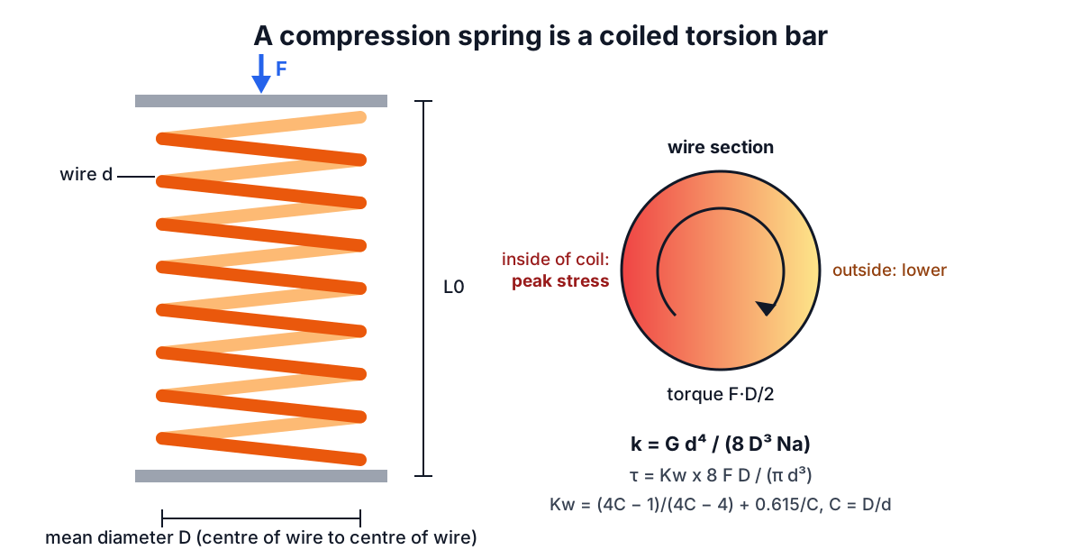
Now unroll the active coils into a straight bar of length πDNa, where Na is the number of active coils. A round bar of diameter d, shear modulus G and length l under torque T twists through an angle θ = Tl / (GJ), with J = πd⁴/32. The axial deflection of the spring is that twist times the arm D/2:
y = θ x D/2 = (F D/2)(π D Na) / (G π d⁴ / 32) x D/2 = 8 F D³ Na / (G d⁴)
k = F / y = G d⁴ / (8 D³ Na)
That is the spring rate. In N, mm and MPa it comes out in N/mm. The exponents make the rate very sensitive to the two diameters: a wire 10% thicker gives a spring 46% stiffer, and a coil 10% larger gives one 25% softer. It also explains the most common measuring error. Use the outside diameter in place of the mean diameter and, for a 2 mm wire in an 18 mm OD coil, the rate comes out 30% too low, because (16/18)³ = 0.70.
The derivation ignores the direct shear and the small change in coil angle under load, which is why the formula is accurate to a few percent for springs with a reasonable pitch and index.
Shear stress and the Wahl factor
The nominal torsional stress in the wire is the torque over the polar section modulus:
τ_nominal = (F D/2) x (d/2) / J = 8 F D / (π d³)
Two effects push the real peak higher. The direct shear F adds to the torsional shear on the inside of the coil and subtracts on the outside, and the wire is curved, so the inner fibres are shorter and strain more for the same twist, like the inside of a curved beam. In 1929 A. M. Wahl combined both into one correction factor using the spring index C = D/d:
Kw = (4C - 1) / (4C - 4) + 0.615 / C
τ = Kw x 8 F D / (π d³)
At C = 8, Kw = 1.184, so the true peak stress is 18% above nominal. At C = 4 it is 1.404, a 40% penalty, which together with manufacturing difficulty is why spring makers prefer an index between about 4 and 12. Shigley's current editions use the Bergsträsser factor, KB = (4C + 2) / (4C − 3), which is within about 1% of Wahl at C = 8 and under 2% at C = 4, with Wahl slightly more conservative. Either is fine for static design.
For the page default in the calculator, a 2 mm music-wire spring with an 18 mm OD (mean diameter 16 mm, C = 8) at 50 N:
τ = 1.184 x 8 x 50 x 16 / (π x 2³) = 301.5 MPa
End types, active coils and solid height
Not every coil deflects. The ends of a spring are usually closed (squared) so it sits flat, and often ground flat as well. Coils that rest on the next coil or on the seat carry no deflection, so they do not count as active. The usual rules, from Shigley Table 10-1:
| End type | Active coils Na | Solid height Ls | Free length L0 |
|---|---|---|---|
| Plain | Nt | d (Nt + 1) | p Na + d |
| Plain and ground | Nt − 1 | d Nt | p (Na + 1) |
| Squared (closed) | Nt − 2 | d (Nt + 1) | p Na + 3d |
| Squared and ground | Nt − 2 | d Nt | p Na + 2d |
Here Nt is total coils and p the pitch. Squared and ground ends are the norm for anything that has to sit square and push straight; they cost a grinding operation and remove two coils from the active count. The calculator's default spring has 10 total coils, so 8 active, a rate of
k = 81,700 x 2⁴ / (8 x 16³ x 8) = 4.99 N/mm
a solid height of 2 x 10 = 20 mm, and with a 44 mm free length, 24 mm of travel before it goes solid. Real solid height is often slightly more than these formulas give, because the ground ends are not perfectly flat and the wire diameter has tolerance. Spring makers often quote a maximum solid height on drawings for that reason.
Strength: allowable stress and the solid-safe check
Spring wire is very strong, and its strength rises as the diameter falls because drawing to a smaller size works the steel harder. Shigley Table 10-4 fits this with Sut = A / d^m. Typical constants with d in mm and Sut in MPa:
| Wire | G (GPa) | A (MPa·mm^m) | m | Allowable static shear |
|---|---|---|---|---|
| Music wire, ASTM A228 | 81.7 | 2,211 | 0.145 | 45% of Sut |
| 302 stainless, ASTM A313 (to 2.5 mm) | 69.0 | 1,867 | 0.146 | 35% of Sut |
| Chrome-vanadium, ASTM A231 | 77.2 | 2,005 | 0.168 | 50% of Sut |
| Chrome-silicon, ASTM A401 | 77.2 | 1,974 | 0.108 | 50% of Sut |
The allowable column is Shigley Table 10-6 for static compression springs without set removal. For 2 mm music wire, Sut = 2,211 / 2^0.145 = 2,000 MPa and the allowable shear is 900 MPa.
The key check is not at the working load but at solid height. Someone will eventually press the spring flat during assembly, and if the stress at solid exceeds the allowable, the spring takes a permanent set and never returns to its free length. A spring that survives being pressed solid is called solid-safe. For the default spring:
force to solid   = 4.99 x 24 = 119.7 N
stress at solid  = 301.5 x 119.7 / 50 = 722 MPa
safety factor    = 900 / 722 = 1.25
Shigley suggests at least 1.2, so it passes. The same geometry in 302 stainless does not: G drops to 69.0 GPa, the allowable falls to 35% of a lower Sut (591 MPa), and the stress at solid of 610 MPa exceeds it. Presetting (compressing past the elastic limit during manufacture) and shot peening raise usable stress, but only if specified.
Buckling and other limits
A long, slender compression spring can bow sideways like a column. Shigley gives the critical free length as
L0 < 2.63 D / α
where α depends on the end conditions. For squared and ground ends on parallel flat plates, α = 0.5, so the limit is about 5.26 times the mean diameter: 84 mm for the default spring. One end free to tilt raises α and lowers the limit sharply. Springs longer than the limit should run on a guide rod or inside a bore, with clearance for the diameter growth that happens as the coils close.
Other practical limits:
- Active coils. Shigley recommends 3 to 15. With very few, the end effects make the rate unpredictable; with very many, the spring is long and buckles.
- Clash allowance. Design so the maximum working deflection leaves 10 to 15% of the travel before solid, so coils do not clash in service.
- Fatigue. Springs that cycle need the Goodman or Sines criterion with endurance data (Zimmerli's values for peened and unpeened wire). Static allowables are not enough for valve springs or anything vibrating.
- Temperature and corrosion. Music wire loses strength above about 120 °C; chrome-silicon and stainless tolerate more. Stainless is chosen for corrosion and food contact as much as strength.
A design workflow
Start from what the spring must do: the force at a working length, the space it has to fit (bore or rod diameter), and the stroke. Pick a material and an index around 6 to 10, choose a wire size, then adjust coils until the rate gives the force at the working length. Check that the stress at solid is under the allowable, that the free length is under the buckling limit, and that the spring fits in the bore with room for the OD to grow. Iterate wire size if any check fails. The Spring Calculator shows all of these at once, so each change shows its effect on every check.
For the material side of the stress calculation, the Stress and Strain Calculator covers elastic moduli and Hooke's law. Springs used to keep preload in bolted joints connect to the Bolt Torque Calculator and the post on bolt tightening torque and preload. Hydraulic return springs size against cylinder force from the Hydraulic Cylinder Calculator.
Material properties here are typical published values and vary by supplier, diameter and heat treatment. Treat results as preliminary, confirm with the spring maker, and have springs in safety-critical service checked by a qualified engineer.