
Duct Sizing: The Velocity and Equal-Friction Methods Explained
How duct friction is calculated from Darcy-Weisbach and Colebrook, what friction rate and velocity to design for, and how the Huebscher formula converts round to rectangular.
· 10 min read

A duct system works when every room gets its design airflow, the fan has enough pressure to push it there, and nobody hears it. Duct size controls all three. Too small and air velocity, noise and pressure loss climb; too large and the ducts cost more, take up space and lose more heat through their surface. This post explains the two classic sizing methods, how duct friction is actually calculated, and how to convert a round size into a rectangle that carries the same air, using the Duct Size Calculator.
Method one: pick a velocity
Continuity says airflow equals area times average velocity, Q = A x V. Choose a velocity and the area, and therefore the diameter of a round duct, follow:
D = √(4Q / πV)
In US units with Q in cfm and V in fpm, the diameter in inches is 13.54 x √(Q/V). For 1,000 cfm at 900 fpm:
D = 13.54 x √(1,000 / 900) = 14.27 in
The velocity method directly controls noise and is easy to apply. Its weakness is that it says nothing about pressure. Two ducts at the same velocity but very different diameters have different friction per foot, so a system sized purely by velocity can end up with some runs starved and others over-supplied.
Typical design velocities are a matter of practice rather than code. For homes, supply trunks are commonly 700 to 900 fpm and branches and returns 500 to 700 fpm; above about 900 fpm noise at grilles becomes noticeable. Commercial low-velocity mains often run 1,000 to 1,500 fpm with branches at 600 to 1,000. Quiet spaces such as studios and bedrooms are kept lower. The ASHRAE Handbook (HVAC Applications) relates velocity to noise criteria in detail.
Method two: equal friction
The equal-friction method picks a pressure loss per unit length and sizes every duct to that rate. Because each run loses pressure at a similar rate per foot, the longest run sets the fan's static pressure requirement, and shorter runs need only modest balancing. Residential systems are commonly designed between 0.06 and 0.10 in.wg per 100 ft (roughly 0.5 to 0.8 Pa/m). ACCA Manual D goes a step further: it subtracts the losses of coils, filters and grilles from the blower's available static pressure and divides what remains by the total effective length of the longest run to get the friction rate for that particular system.
To size by friction you need a way to calculate it. The Darcy-Weisbach equation gives the pressure gradient in a round duct:
Δp / L = (f / D) x ρV² / 2
where ρ is air density and f the Darcy friction factor. For turbulent flow f comes from the Colebrook equation:
1/√f = −2 log10( ε/(3.7 D) + 2.51/(Re √f) )
Re is the Reynolds number ρVD/μ and ε the absolute roughness of the duct wall. Colebrook is implicit in f, so the calculator solves it by iteration, then solves for the diameter that gives your target friction by bisection. It uses ASHRAE standard air (1.204 kg/m³ at 20 °C and sea level) and the roughness categories from ASHRAE Fundamentals: galvanized steel is "medium smooth" at 0.09 mm (0.0003 ft), the basis of the ASHRAE friction chart; PVC and aluminium are about 0.03 mm; fibrous glass duct board about 0.9 mm; and flexible duct, even fully stretched, about 3 mm.
For 1,000 cfm at 0.1 in.wg per 100 ft in galvanized steel:
exact diameter  13.65 in
velocity        about 980 fpm
Reynolds number about 115,000 (fully turbulent)
next standard   14 in round
That agrees with a reading off the ASHRAE friction chart or a duct slide rule. Rounding up to 14 in drops the friction to about 0.088 in.wg per 100 ft.
Roughness matters more than people expect. The same 1,000 cfm in fully stretched flex duct (3 mm roughness) needs about 15.5 in for the same friction instead of 13.65 in, and flex that is compressed or sagging can have several times the friction of the stretched value. Keep flex runs short and pulled tight.
From round to rectangular: the Huebscher formula
Space often forces a rectangular duct. A rectangle with the same area as a round duct does not carry the same air at the same friction, because its corners add wetted perimeter where the air slows down. Huebscher (1948) derived the equivalent diameter of a rectangle a x b, meaning the round duct that has the same friction and the same airflow:
De = 1.30 x (a x b)^0.625 / (a + b)^0.25
Some checks against ASHRAE's tabulated values: 12 x 12 in gives 13.1 in, 24 x 12 gives 18.3 in, 10 x 8 gives 9.8 in. The calculator inverts the formula numerically to find the width for each standard height.
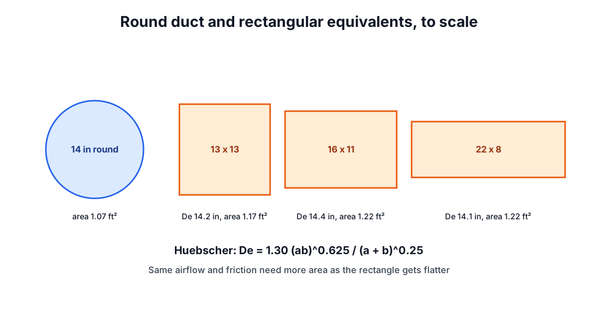
The drawing makes the cost of flat ducts visible. A 14 in round has an area of 1.07 ft². The 13 x 13 square needs 1.17 ft² and the 22 x 8 needs 1.22 ft² to do roughly the same job, with more sheet metal per foot as well. That is why aspect ratios above about 4:1 are avoided. The calculator greys out options beyond 4:1 and hides those beyond 8:1.
Note that equal friction does not mean equal velocity. The rectangle has a larger area than the round, so its velocity is lower, which the calculator shows in the table.
Beyond the straight duct
The friction rate covers straight duct only. Fittings usually add as much loss again, sometimes more. Each elbow, tee, transition or damper has a loss coefficient C, and its pressure loss is C times the velocity pressure:
velocity pressure = ρV² / 2     (Pa)
                  = (V / 4,005)² (in.wg, V in fpm, standard air)
At 980 fpm the velocity pressure is about 0.06 in.wg, so a fitting with C = 0.3 costs 0.018 in.wg, the same as 18 ft of straight duct at 0.1 per 100 ft. Manual D and the ASHRAE Duct Fitting Database express these as equivalent lengths that are added to the straight run.
Other points to check before installation:
- Altitude and temperature. Air is less dense at altitude and when hot. Friction at the same cfm drops, but so does the mass of air and the heat it carries.
- Leakage. Unsealed seams lose air before it reaches the room. Sealing to the standard required by your energy code matters as much as sizing.
- Returns. Undersized returns are one of the most common causes of low airflow and noise. Size them with the same care as supplies.
- Heat loss and gain. Ducts outside the conditioned space need insulation; the post on U-values and heat loss shows the calculation.
Getting the airflow in the first place
Duct sizing starts from the airflow each room needs. That comes from a room-by-room load calculation (ACCA Manual J or equivalent), roughly 400 cfm per ton of cooling for typical equipment. The BTU Calculator gives a first estimate of the load, and the Air Changes per Hour Calculator turns airflow into air changes for ventilation checks, explained further in the post on air changes per hour. For the fluid mechanics in more depth, see the Reynolds Number Calculator and the Pipe Pressure Drop Calculator, which apply the same Darcy-Weisbach and Colebrook approach to liquids.