
Fillet Weld Size and Strength: Throat, AISC LRFD and ASD
How a fillet weld carries load through its throat, the AISC 360 equations with φ and Ω, the directional increase, size limits, a worked bracket example and filler metal estimates.
· 10 min read
The fillet weld is the workhorse of steel fabrication. It needs no edge preparation, it fits almost any joint where two plates meet at an angle, and it makes up the large majority of welds in buildings, machinery and equipment. Sizing one is straightforward once you see how it carries load: through a thin plane called the throat. This post walks through the throat geometry, the AISC 360 strength equations in both LRFD and ASD form, the directional strength increase, the code limits on size, a worked bracket example, and how to estimate the weld metal and filler you will burn. Everything here can be reproduced in the Weld Size Calculator.
The throat: where a fillet weld fails
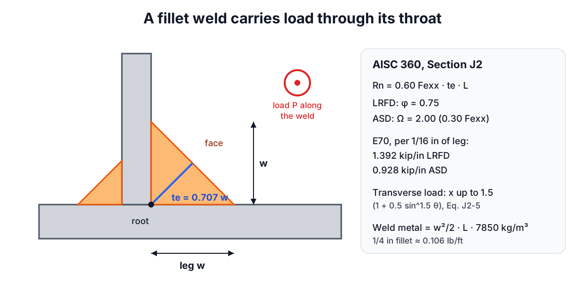
An equal-leg fillet weld has a triangular cross-section. The two legs, w, lie along the faces of the joined parts, and the face of the weld runs diagonally between their ends. When a fillet weld is overloaded it tears along the shortest path through the weld metal, from the root of the joint to the face. That shortest distance is the throat:
effective throat te = w x cos 45° = 0.707 x w
A 1/4 in fillet has a throat of 0.177 in, a 6 mm fillet 4.24 mm. AISC 360 defines the effective throat as the shortest distance from the root to the face of the diagrammatic weld, which for an equal-leg flat or slightly convex fillet is exactly this. Any extra convexity above the flat face adds weld metal but is not counted as strength.
The AISC strength equations
AISC 360 Section J2.4 gives the nominal strength of a fillet weld as the throat area times the nominal stress of the weld metal:
Rn  = Fnw x Awe
Fnw = 0.60 x Fexx           (load along the weld axis)
Awe = te x L
Fexx is the electrode classification strength: 70 ksi for E70XX, which is the default for most structural work with A36 and A992 steel. The design value depends on the method:
LRFD:  φ Rn   with φ = 0.75      →  0.45 Fexx x te x L
ASD:   Rn / Ω with Ω = 2.00      →  0.30 Fexx x te x L
The ASD form is the classic “0.3 Fexx on the throat” rule from older allowable stress codes. Because te = 0.707 w, the strength per inch of a fillet with leg in sixteenths of an inch has a convenient constant. For E70:
LRFD: 0.75 x 0.60 x 70 x 0.707 / 16 = 1.392 kip/in per sixteenth
ASD:  0.30 x 70 x 0.707 / 16        = 0.928 kip/in per sixteenth
So a 1/4 in (four sixteenths) E70 fillet is good for 5.57 kip per inch in LRFD and 3.71 kip per inch in ASD. These are the constants printed in the AISC Steel Construction Manual design tables, and they are the quickest way to check any calculator, including this one.
Load direction and the directional strength increase
Tests show that a fillet weld loaded across its axis is stronger than one loaded along it. AISC Equation J2-5 captures this:
Fnw = 0.60 Fexx x (1.0 + 0.50 sin^1.5 θ)
where θ is the angle between the load and the weld’s longitudinal axis. At θ = 0 the factor is 1.0, at 45° about 1.30, and at 90° (a transverse weld) 1.5. The catch is that transverse welds are also less ductile, so when a weld group mixes longitudinal and transverse welds, the stiffer transverse welds reach their limit before the longitudinal ones develop their full strength. AISC restricts the full increase accordingly and gives a separate rule for such groups. Unless you know the rule applies to your joint, design with θ = 0, which is conservative.
Minimum and maximum sizes
Strength is not the only consideration.
Minimum size. A small weld on thick plate cools very quickly because the plate sinks the heat away, and fast cooling makes the weld prone to cracking. AISC Table J2.4 sets the minimum leg by the thinner part joined:
| Thinner part | Minimum fillet |
|---|---|
| up to 1/4 in | 1/8 in |
| over 1/4 to 1/2 in | 3/16 in |
| over 1/2 to 3/4 in | 1/4 in |
| over 3/4 in | 5/16 in |
Maximum along an edge. Along the edge of a part, AISC J2.2b limits the leg to the thickness of the part when it is under 1/4 in, and to the thickness minus 1/16 in for thicker material, so the inspector can still see the edge.
Minimum length. The effective length of a fillet should be at least four times its leg size, otherwise its effective size is taken as a quarter of its length.
A worked example
A clip angle is welded to a column with two vertical fillet welds, each 5 in long, carrying a factored vertical load of 30 kip along the welds. E70 electrodes, LRFD. The thinner part is the 1/2 in angle leg.
required φRn per inch of weld = 30 / (2 x 5)              = 3.0 kip/in
leg required = 3.0 / (0.75 x 0.60 x 70 x 0.707)          = 0.135 in
round up to 1/16 in                                       → 3/16 in
check minimum for 1/2 in part (Table J2.4)                = 3/16 in  OK
capacity with 3/16 in:  3 x 1.392 x 10                    = 41.8 kip
The weld is controlled by the minimum size rather than by strength. Using a 1/4 in fillet “to be safe” would add 78% more weld metal for no structural benefit: weld volume grows with the square of the leg. A complete design would also check the shear strength of the base metal at the fusion faces and the angle and column themselves, as AISC Section J4 requires.
In metric terms the same approach gives about 0.92 kN per mm of a 6 mm E70 fillet in LRFD. Eurocode users work instead with EN 1993-1-8, whose simplified method uses a design shear strength of (fu / √3) / (βw x γM2), with a correlation factor βw that depends on the steel grade. The ideas are the same; the numbers differ, so follow the code that governs your project.
How much weld metal and filler
For costing and ordering, the weight of weld metal comes from the cross-section:
area of a flat equal-leg fillet = w² / 2
weld metal = area x length x density (7,850 kg/m³ for steel)
A 1/4 in fillet has an area of 0.03125 in², which is 0.106 lb of steel per foot of weld; a 6 mm fillet holds 0.141 kg per metre. Real welds are slightly convex, so estimators add 10 to 20% for convexity and overfill.
Not all of the filler you buy ends up in the joint. Deposition efficiency covers stub ends, slag, spatter and fume:
| Process | Typical deposition efficiency |
|---|---|
| SMAW stick, 2 in stub loss | about 60% |
| GMAW solid wire | about 95% |
| FCAW gas shielded | about 85% |
| FCAW self shielded | about 82% |
| SAW submerged arc | about 99% |
So 1 m of 6 mm fillet with 10% overfill needs 0.155 kg of weld metal, which is about 0.26 kg of stick electrodes or 0.16 kg of MIG wire. On a job with hundreds of metres of weld, that difference is worth knowing before ordering.
Common mistakes
- Mixing LRFD and ASD. Factored loads go with φ = 0.75; service loads go with Ω = 2.00. Using a factored load with ASD overdesigns by roughly 40 to 60%; the reverse is unsafe.
- Using the leg instead of the throat. Multiplying 0.3 Fexx by the leg overstates the strength by 41%.
- Counting the weld but not the metal it joins. Thin plates and the base metal at the fusion face can govern.
- Oversizing. Bigger welds distort the work, cost more and are more likely to contain defects.
- Ignoring quality. Undercut, lack of fusion and porosity reduce strength regardless of size; inspection and a qualified procedure matter as much as the calculation.
For the bolted alternative, see the bolt torque calculator. If the weld closes the seam of a rolled cone, the cone flat pattern guide covers the layout, and the sheet metal weight calculator gives the weight of the parts being joined.