
Bearing L10 Life Explained: ISO 281 Rating Life, Loads and Reliability
The cube law behind bearing life, how to get the equivalent load from radial and axial forces, the ISO 281 a1 reliability factors and how to size a bearing for a target life.
· 10 min read

A ball bearing running on a clean, well-lubricated shaft does not wear out gradually like a brake pad. It runs quietly for a long time and then, at some point, a small flake of steel lifts out of a raceway where millions of contact stress cycles have grown a crack under the surface. That moment is random. Two bearings from the same box, on the same machine, can fail years apart. Bearing life calculations therefore do not predict when one bearing will fail; they predict the life that a stated percentage of a large population will reach. This guide explains the ISO 281 method behind the Bearing Life Calculator, how to get the numbers into it, and how to read what comes out.
The rating life equation
ISO 281 defines the basic rating life L10 as the number of revolutions that 90% of a group of apparently identical bearings will complete or exceed before the first evidence of fatigue. It is calculated from two loads:
L10 = (C / P)^p      (millions of revolutions)
p = 3      for ball bearings
p = 10/3   for roller bearings
C is the basic dynamic load rating, a number printed in every bearing catalogue. It is the load at which the bearing would reach an L10 life of exactly one million revolutions. P is the dynamic equivalent load actually applied. Because C is calculated to the same standard by every major manufacturer, you can compare bearings from different brands on C alone, as long as they are the same type and quality.
To get hours at a steady speed n in rpm:
L10h = 1,000,000 × L10 / (60 × n)
The equation comes from the fatigue theory published by Gustaf Lundberg and Arvid Palmgren at SKF in 1947 and 1952, which treated subsurface fatigue as a weakest-link problem with a Weibull distribution. The exponents came from fitting extensive endurance test data: point contact in ball bearings gave a cube law, and line contact in roller bearings a slightly steeper 10/3 power.
Why the cube law matters
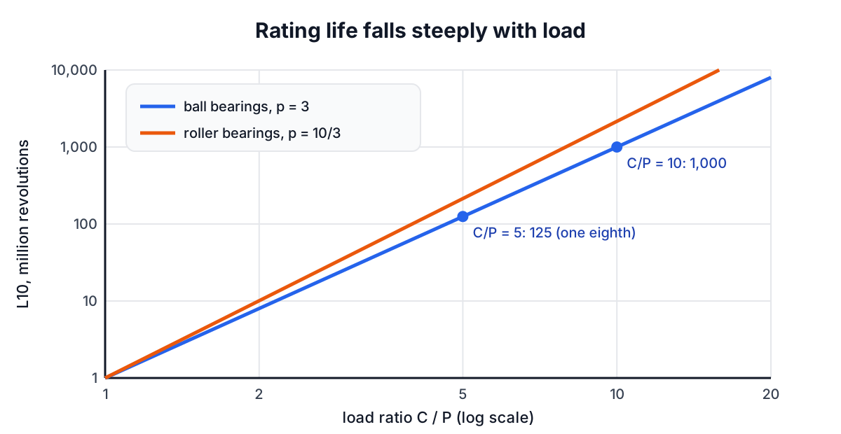
The exponent makes life brutally sensitive to load. For a ball bearing:
- 10% more load cuts life by 25% (1 / 1.1³ = 0.75).
- 26% more load halves it.
- Twice the load cuts it to one eighth.
For a roller bearing the effect is even stronger: twice the load divides life by 2^(10/3), about 10. That is why a small error in estimating the load, such as forgetting belt pretension on a pulley shaft or the separating force of helical gears, matters far more than the bearing's catalogue rating. It is also why the first fix for a short-lived bearing is usually to find the load you missed, not to buy a premium brand.
Getting the equivalent load P
Most bearings see a radial load Fr and some axial load Fa at the same time. ISO 281 combines them into a single equivalent radial load that would give the same life:
P = X · Fr + Y · Fa
X and Y depend on the bearing type and on how large the axial load is relative to the radial one. For a deep groove ball bearing, the catalogue gives a limit e (typically 0.2 to 0.45, depending on f0·Fa/C0). When Fa/Fr is at or below e, X = 1 and Y = 0, so the axial load is ignored. Above e, X = 0.56 and Y runs from about 1.0 to 2.3. Angular contact, taper roller and spherical roller bearings have their own tables.
Example from the calculator: Fr = 3 kN and Fa = 1.2 kN on a deep groove bearing with X = 0.56 and Y = 1.6 gives P = 1.68 + 1.92 = 3.6 kN. With C = 14.8 kN at 3,000 rpm, L10 = (14.8 / 3.6)³ = 69.5 million revolutions, or 386 hours. The axial load, smaller than the radial one, contributes more than half of P.
When the load varies over a duty cycle, do not use the peak or the arithmetic average. Use the cube-mean load:
P_mean = ( Σ Pi³ · Ni / Σ Ni )^(1/3)
where Ni is the number of revolutions at load Pi. A few minutes a day at a heavy load can dominate the result.
Reliability and the a1 factor
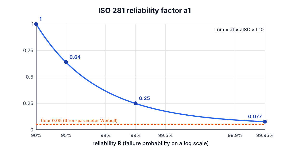
L10 accepts that one bearing in ten will fail before the calculated life. For a machine where a stop is expensive, or where many bearings must all survive, you want a higher reliability, and the life you can promise is shorter. ISO 281 handles this with a life modification factor for reliability a1:
Lnm = a1 × aISO × L10
The 2007 edition of ISO 281 moved to a three-parameter Weibull model in which the life never falls to zero, giving:
a1 = 0.95 × ( ln(100/R) / ln(100/90) )^(2/3) + 0.05
| Reliability R | Life called | a1 (ISO 281:2007) |
|---|---|---|
| 90% | L10m | 1 |
| 95% | L5m | 0.64 |
| 96% | L4m | 0.55 |
| 97% | L3m | 0.47 |
| 98% | L2m | 0.37 |
| 99% | L1m | 0.25 |
| 99.9% | L0.1m | 0.093 |
| 99.95% | L0.05m | 0.077 |
Older catalogues based on the 1990 edition used a two-parameter model and print 0.62, 0.53, 0.44, 0.33 and 0.21 for 95 to 99%. The difference is small at common reliability levels and grows above 99%. The calculator uses the 2007 table.
The aISO factor accounts for lubrication, contamination and the fatigue load limit. With a thick oil film and very clean oil it can be several times 1; with marginal lubrication and dirty grease it can be 0.1 or lower. It is calculated from the viscosity ratio κ and a contamination factor using charts in ISO 281 or the bearing maker's software. The calculator accepts it as an input and leaves it at 1 unless you have a figure.
A full sizing example
A fan shaft runs at 1,500 rpm with a radial load of 2 kN on its drive-end bearing. The machine runs 8 hours a day and the design target is 20,000 hours.
- Try a 6205 deep groove ball bearing, catalogue C = 14.8 kN. C/P = 7.4.
- L10 = 7.4³ = 405.2 million revolutions.
- L10h = 405.2 × 10⁶ / (60 × 1,500) = 4,502 hours, about 1.5 years at 8 hours a day.
- Required C for 20,000 hours: L10 = 20,000 × 60 × 1,500 / 10⁶ = 1,800 million revolutions, so C = 2 × 1,800^(1/3) = 24.3 kN.
- A 6305 (C = 23.4 kN in the SKF catalogue) falls just short; a 6306 (about 29.6 kN) meets it with margin. Check the shaft size and speed rating before choosing.
- If the owner wants 99% reliability, divide by a1 = 0.25 first: C = 2 × (1,800 / 0.25)^(1/3) = 38.6 kN, a much larger bearing.
The calculator does steps 2 to 6 at once and shows the life at every reliability level in a table.
When the rating life is the wrong question
The rating life covers one failure mode, subsurface rolling contact fatigue, under good conditions. Field failures are more often caused by something else:
- Contamination and poor lubrication. Dents from particles and metal-to-metal contact start surface fatigue far earlier. This is what aISO tries to capture.
- Static overload and slow speeds. Below about 10 rpm, or for oscillating motion, size by the static rating C0 instead, since fatigue cycles are few but brinelling is a risk.
- Very light loads. Rolling elements can skid instead of roll. A common rule is a minimum load of about 1% of C for ball bearings and 2% for roller bearings.
- Misalignment, fit and temperature. A tight fit or thermal growth can remove internal clearance and preload the bearing heavily, changing P without anyone noticing.
- Electrical current. Variable-frequency drives can pass current through motor bearings and flute the races.
Typical design targets give a sense of scale. SKF's guideline values run from a few hundred to 3,000 hours for household appliances, 10,000 to 25,000 hours for machines working one shift, 40,000 to 50,000 hours for continuous plant, and 100,000 hours or more for paper machines and similar equipment.
Related tools and guides
Bearing loads usually come from something else in the drive. Work out shaft torque with the Torque and Power Calculator, gear loads and speeds with the Gear Ratio Calculator, and belt pull with the Pulley and Belt Calculator. For the stress side of shaft design, the stress and strain guide covers axial loading, and the speeds and feeds guide explains why spindle bearings set the RPM limit on a machine tool. Bearing calculations here are for preliminary selection; confirm the final choice with the manufacturer's tools and a qualified engineer.