
Hydraulic Cylinder Force, Speed and Flow: The Sizing Maths
Pascal’s law applied to a double-acting cylinder: push and pull force, extend and retract speed, the area ratio that catches people out, regeneration and pump power.
· 9 min read
A hydraulic cylinder is one of the simplest machines in engineering: a tube, a piston and a rod. Yet sizing one goes wrong surprisingly often, usually because the two sides of the piston are treated as if they were the same. This guide works through the arithmetic behind the Hydraulic Cylinder Calculator: where push and pull force come from, why the cylinder moves at two different speeds, how much oil and power each stroke costs, and what changes in a regenerative circuit. The numbers are exact enough for preliminary sizing; the judgment calls about pressure losses, buckling and mounting are covered at the end.
Pressure times area: the force equation
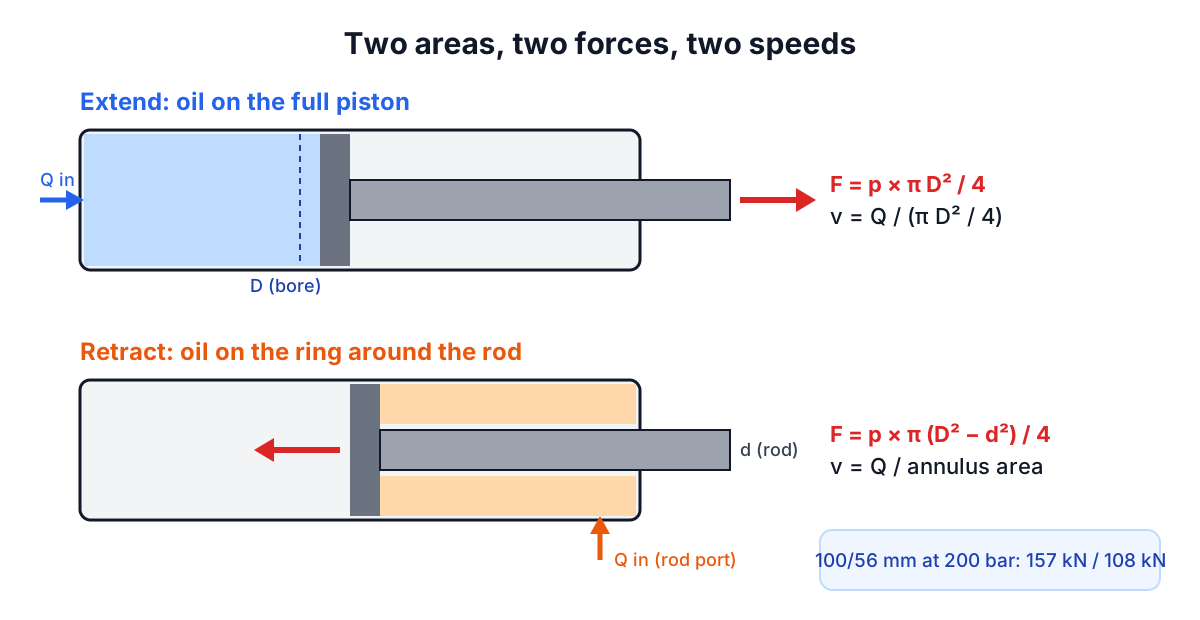
Pascal's law says pressure in a confined fluid acts equally in all directions. Push oil at pressure p into the cap end of a cylinder and it presses on the whole piston face. The force is:
F_extend = p × A_piston = p × π D² / 4
On the rod side, the oil presses on a ring, the annulus between the bore and the rod:
F_retract = p × A_annulus = p × π (D² − d²) / 4
D is the bore and d is the rod diameter. Units need care, so here are the ones that come up most:
- Metric: 1 bar = 0.1 N/mm². Force in newtons = bar × mm² / 10. A 100 mm bore has 7,854 mm², so at 200 bar it pushes 157,080 N, or 157.1 kN.
- US: psi × in² gives pounds-force directly. A 3 in bore has 7.069 in², so at 2,500 psi it pushes 17,671 lbf.
- MPa: 1 MPa = 10 bar = 1 N/mm², which is convenient because force in N = MPa × mm².
The conversions the calculator uses are exact: 1 psi = 6.894757 kPa (from the definitions of the pound and the inch), and 1 US gallon = 231 in³ = 3.785411784 L.
Flow divided by area: the speed equation
The pump delivers a volume of oil per minute, Q. The piston has to move far enough to make room for it:
v_extend = Q / A_piston
v_retract = Q / A_annulus
In metric, convert L/min to mm³/s by multiplying by 1,000,000 / 60. For the 100 mm bore at 40 L/min: 666,667 mm³/s / 7,854 mm² = 84.9 mm/s. In US units, one gallon is 231 in³, so speed in in/s = 231 × gpm / (60 × area in in²). A 3 in bore at 10 gpm extends at 5.45 in/s.
Reverse the formula to find the pump you need: Q = A × v. A shortcut worth memorising in metric is L/min = area in cm² × speed in m/min / 10. A 100 mm bore (78.5 cm²) extending at 6 m/min needs 47 L/min.
The area ratio and why retraction surprises people
Because the annulus is smaller than the piston, the same flow moves the piston faster on the way back, with less force. The ratio of the two areas, often written φ (phi), sets the size of the difference:
φ = A_piston / A_annulus = D² / (D² − d²)
For a 100 mm bore with a 56 mm rod, φ = 1.457. So:
- Retract speed is 1.457 × 84.9 = 123.7 mm/s.
- Retract force is 157.1 / 1.457 = 107.8 kN.
- While retracting, the oil leaving the cap end is 1.457 × 40 = 58.3 L/min.
That last number is the one that catches people. The return line, return filter and directional valve all see more flow than the pump makes. Size them for the pump flow alone and you get back pressure, heat and, at worst, a burst return filter.
Rod size is mostly chosen for buckling and for the force needed in the pull direction. Catalogue rod options for a given bore typically give φ between about 1.25 and 2, and picking a standard ratio makes it easier to match speeds and to design regenerative circuits.
Regenerative circuits
In a regenerative circuit the oil leaving the rod side during extension is piped back into the cap side instead of returning to the tank. The net area the pump has to fill is just the rod area, so:
v_regen = Q / A_rod
F_regen = p × A_rod
For a 63 mm bore with a 36 mm rod at 160 bar and 20 L/min, normal extension gives 106.9 mm/s and 49.9 kN. Regeneration gives 327.5 mm/s and 16.3 kN. With a 2:1 area ratio (rod area equal to half the piston area), regenerative extension and normal retraction run at the same speed, which is the classic reason for that rod size. Presses and log splitters often switch from regenerative to normal extension automatically when the pressure rises, giving a fast approach and a strong final push.
Power, cycle time and oil volume
Hydraulic power is pressure times flow:
kW = bar × L/min / 600
hp = psi × gpm / 1714
The 200 bar, 40 L/min example needs 13.3 kW of hydraulic power; the 2,500 psi, 10 gpm log splitter needs 14.6 hp. Divide by the pump's overall efficiency, often 0.85 to 0.9, to size the motor or engine. Many small power units use a two-stage pump precisely because full flow at full pressure would need an engine twice the size.
Stroke time is stroke length divided by speed, and the cycle time is the sum of extend and retract times. The 100/56 cylinder with a 500 mm stroke takes 5.89 s to extend and 4.04 s to retract, a 9.93 s cycle. Real cycles are longer: valves take time to shift, the load has to accelerate, and pressure has to build at the end of each stroke. Oil volume per stroke, A × stroke, tells you how much the reservoir level will swing as the cylinder extends, which matters with large cylinders and small tanks.
Worked sizing example
A fixture needs a clamp force of 50 kN from a power unit set to 160 bar.
- Required area: A = F / p = 50,000 / 16 = 3,125 mm².
- Bore: D = √(4A / π) = 63.1 mm. A 63 mm cylinder gives 49.9 kN, which has no margin at all once friction and pressure drop are included. Choose 80 mm, which gives 80.4 kN at 160 bar, or keep 63 mm and raise the pressure if the unit allows.
- Rod: 45 mm on the 80 mm bore gives φ = 1.46 and 55.0 kN of pull, ample for unclamping.
- Speed: the clamp must close 100 mm in 2 s, so 50 mm/s. Q = 5,027 mm² × 50 mm/s = 251,000 mm³/s = 15.1 L/min.
- Power: 160 × 15.1 / 600 = 4.0 kW hydraulic.
The calculator does all of this if you enter the bore, rod, pressure and a target speed.
What the simple model leaves out
The textbook equations give theoretical values. Before relying on them:
- Pressure at the cylinder is lower than at the pump. Hoses, valves and fittings can drop 5 to 20 bar at full flow. Use the Pipe Pressure Drop Calculator for long lines.
- Back pressure subtracts. Any pressure on the outlet side, from a return filter or a counterbalance valve, pushes the other way on the opposite area.
- Seal friction. Expect 90 to 95% of theoretical force from a typical cylinder, less at low pressure. The calculator's efficiency field derates force but not speed.
- Rod buckling. A long rod in push is a column. Check it with the Column Buckling Calculator using the effective length for your mounting style, and apply a generous factor because side loads and wear add bending.
- Leakage and flow controls. Internal leakage slows the cylinder under load, and any meter-in or meter-out valve sets speed independently of the pump.
Related tools and guides
Pump sizing continues with the Pump Power Calculator and flow conversions with the Flow Rate Calculator. For the solid mechanics of rods and tie bars, see the stress and strain guide, and for machine elements that the cylinder may drive, the bearing life guide. The calculator is intended for preliminary sizing; hydraulic systems store a lot of energy, so have a qualified engineer check the final design against the cylinder maker's ratings and the applicable machinery safety standards.