
NEC Conduit Fill Explained: The 53, 31 and 40 Percent Rules
How NEC Chapter 9 Tables 1, 4, 5 and 8 fit together, why two wires get only 31%, the Note 7 rounding behind Annex C, mixed-size fills, cables, nipples and what fill does not cover.
· 10 min read

Conduit fill is one of the first things an inspector checks and one of the easiest to get wrong from memory. The rule people quote, "40 percent", is only one of three limits, and the areas it applies to change with the raceway type and the insulation on the wire. This guide walks through the National Electrical Code (NFPA 70) Chapter 9 method from start to finish, with worked numbers you can check in the Conduit Fill Calculator. It explains the reasoning so you can follow a design or spot a mistake; your local code edition and the authority having jurisdiction have the final word.
The four tables that do the work
Chapter 9 sits at the back of the NEC and holds the data every fill calculation needs:
- Table 1 gives the percentage of the raceway's cross-section the conductors may occupy.
- Table 4 gives the internal diameter and total internal area of each raceway type, trade size by trade size.
- Table 5 gives the approximate area of insulated building wire by type and size.
- Table 8 gives the dimensions of bare conductors, which you need for bare equipment grounding conductors.
The notes to the tables matter as much as the tables. Note 1 points to Informative Annex C when all conductors are the same size. Note 4 covers short nipples. Note 7 sets a rounding rule. Note 9 says how to treat a multiconductor cable. We will use each of them below.
Table 1: why there are three percentages
| Number of conductors or cables | Maximum fill |
|---|---|
| 1 | 53% |
| 2 | 31% |
| Over 2 | 40% |
The odd one out is two conductors. Picture two round wires side by side in a round pipe: their combined width is twice a wire diameter, and if that approaches the pipe's inside diameter they wedge across it at every bend. A single conductor lies along the bottom of the pipe and can take more of the area. Three or more settle into a loose bundle that pulls predictably at 40%.
Note 4 relaxes the limit to 60% for a nipple, a raceway 24 in (600 mm) or shorter between enclosures. There is no long pull, so the wires can be packed tighter. (Ampacity adjustment for many current-carrying conductors is also waived for nipples under 310.15(C)(1)(b), but that is an ampacity rule, not a fill rule.)
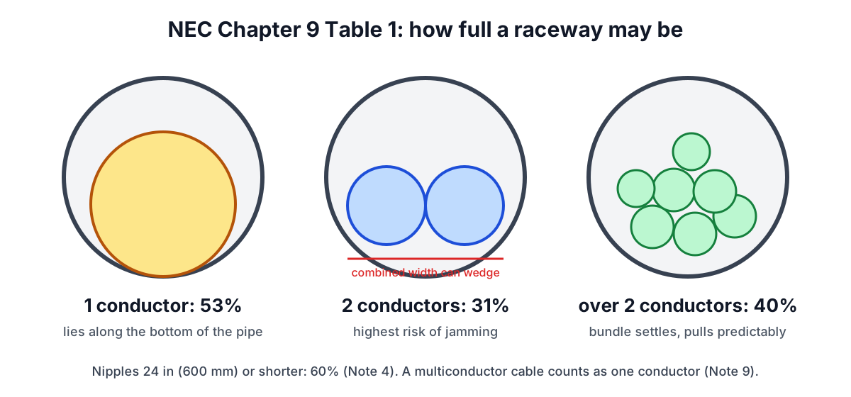
Table 4: the inside of the pipe
Trade sizes are names, not measurements. A "1/2 inch" EMT has an inside diameter of 0.622 in; a "1/2 inch" Schedule 80 PVC has 0.526 in because its wall is thicker. Table 4 lists the real internal area for every type, and the differences are large:
| Trade size | EMT | RMC | IMC | PVC Sch 40 | PVC Sch 80 | FMC |
|---|---|---|---|---|---|---|
| 1/2 | 0.304 | 0.314 | 0.342 | 0.285 | 0.217 | 0.317 |
| 3/4 | 0.533 | 0.549 | 0.586 | 0.508 | 0.409 | 0.533 |
| 1 | 0.864 | 0.887 | 0.959 | 0.832 | 0.688 | 0.817 |
| 1-1/4 | 1.496 | 1.526 | 1.647 | 1.453 | 1.237 | 1.277 |
| 2 | 3.356 | 3.408 | 3.630 | 3.291 | 2.874 | 3.269 |
Areas in square inches (100% column). A 1 in Schedule 80 PVC has 20% less room than a 1 in EMT. Always take the row for the exact raceway you are installing; Schedule 40 PVC values also apply to HDPE.
Table 4 also prints the 40%, 31% and 53% columns, rounded to three decimals. The calculator works from the 100% area, which is how the Annex C tables were generated.
Table 5 and Table 8: the wire
Insulation thickness drives conductor area as much as copper does at small sizes:
| Size | THHN/THWN-2 | XHHW-2 | TW/THW | Bare stranded (Table 8) |
|---|---|---|---|---|
| 14 AWG | 0.0097 | 0.0139 | 0.0139 | 0.004 |
| 12 AWG | 0.0133 | 0.0181 | 0.0181 | 0.006 |
| 10 AWG | 0.0211 | 0.0243 | 0.0243 | 0.011 |
| 8 AWG | 0.0366 | 0.0437 | 0.0437 | 0.017 |
| 6 AWG | 0.0507 | 0.0590 | 0.0726 | 0.027 |
| 4/0 AWG | 0.3237 | 0.3197 | 0.3718 | 0.219 |
Twelve-gauge XHHW takes 36% more room than twelve-gauge THHN. At large sizes the difference narrows, and XHHW is even slightly smaller than THHN at 4/0. If the reel says "THHN/THWN-2" use the THHN column; if it is dual-rated XHHW-2, use XHHW.
Worked example: mixed branch circuits
A 3/4 in EMT carries three 20 A circuits and three 30 A circuits with a shared bare ground: six 12 AWG THHN, three 10 AWG THHN and one 10 AWG bare stranded copper.
- Areas: 6 × 0.0133 = 0.0798 in²; 3 × 0.0211 = 0.0633 in²; 1 × 0.011 = 0.011 in². Total 0.1541 in².
- Ten conductors, so Table 1 allows 40%. 0.533 × 0.40 = 0.2132 in².
- 0.1541 ≤ 0.2132, so the fill passes at 0.1541 ÷ 0.533 = 28.9%, with 0.0591 in² to spare.
Notice that the ground counts. Equipment grounding conductors are not current-carrying for ampacity purposes, but they occupy space and Chapter 9 Note 3 says to include them.
Annex C and the Note 7 rounding
When every conductor is the same size and type, you can skip the arithmetic and read Informative Annex C, which tabulates the maximum count for each raceway and trade size. The tables come from a simple rule: divide the 40% area by one conductor's area and, per Note 7, round up if the decimal is 0.8 or more.
For 12 AWG THHN in EMT: 1/2 in gives 0.1216 ÷ 0.0133 = 9.14, so 9. 3/4 in gives 16.03, so 16. 1-1/4 in gives 0.5984 ÷ 0.0133 = 44.99; the remainder is above 0.8, so 45 are allowed. Annex C Table C.1 lists 9, 16, 26, 45, 61 and 101 for 1/2 through 2 in. The calculator's Annex C panel reproduces these.
Note 7 applies only to same-size conductors. With mixed sizes the total area must be within the limit, with no rounding.
There is one quirk worth knowing. Where the 40% division gives a number between 2 and 3, some cells of Annex C as commonly reprinted show 2 even though two conductors would exceed the 31% limit of Table 1. Six AWG THHN in 1/2 in EMT is the usual example: two conductors need 0.1014 in² and 31% of 0.304 is 0.0942 in². Table 1 is the enforceable rule and Annex C is informative, so the calculator applies Table 1 strictly and reports one. If you are relying on the printed table, raise it with the inspector.
Sizing a feeder
For a feeder you usually know the conductors and want the raceway. Four 4/0 AWG THHN (three phases and a neutral) and a 4 AWG THHN equipment ground:
- 4 × 0.3237 + 0.0824 = 1.3772 in².
- Five conductors, so 40%. Required raceway area at least 1.3772 ÷ 0.40 = 3.443 in².
- PVC Schedule 40: 2 in has 3.291 in² (41.8% fill, fails); 2-1/2 in has 4.695 in² (29.3%, passes).
- EMT: 2 in has 3.356 in², still short; 2-1/2 in with 5.858 in² passes easily.
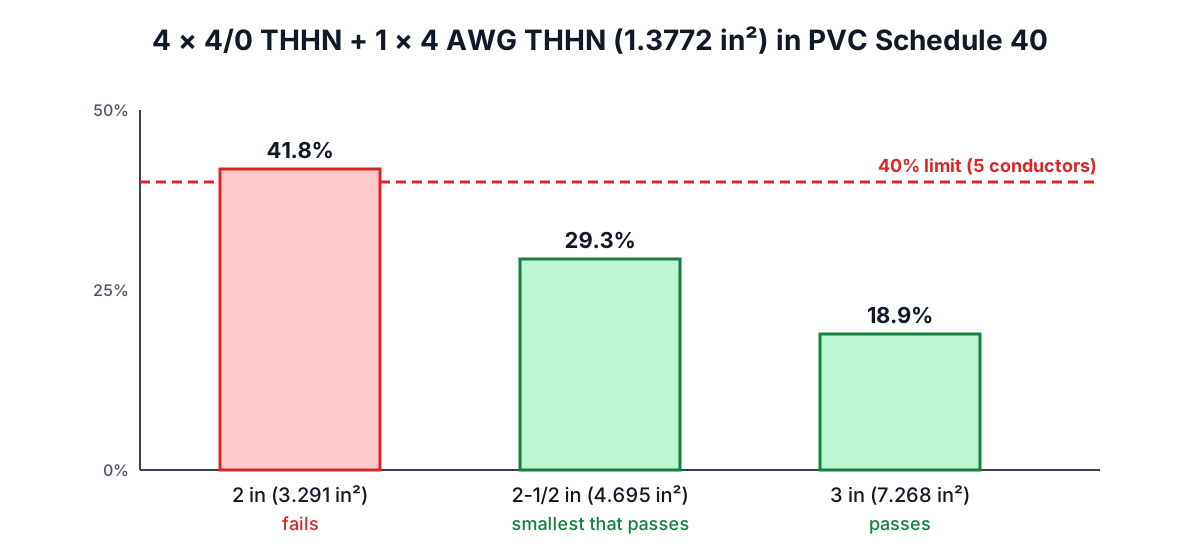
The calculator's size table shows every trade size at once and marks the smallest that passes, which saves stepping through Table 4 by hand.
Cables in conduit
Cable assemblies are often sleeved through a short raceway for protection. Note 9 treats a multiconductor cable as a single conductor whose area comes from its outside diameter. For an elliptical cable such as flat NM, use the major (larger) dimension as the diameter, which makes the cable look like a round one of that width.
One 0.5 in cable in 3/4 EMT: area π/4 × 0.5² = 0.1963 in². One "conductor" means 53% is allowed: 0.2825 in². It fits, at 36.8%. Two such cables would be held to 31% (0.1652 in²) against 0.3927 in², so they would need a 1-1/4 in raceway, where 31% of 1.496 is 0.4638 in².
What fill does not tell you
Passing fill does not make an installation right. Three other checks travel with it:
- Ampacity adjustment. More than three current-carrying conductors in a raceway reduce each one's ampacity: 80% for 4 to 6, 70% for 7 to 9, 50% for 10 to 20 (Table 310.15(C)(1)). Nine circuits in a pipe that passes fill may need larger wire. The Wire Size Calculator applies these factors.
- Jamming. Three conductors whose diameter ratio (raceway ID ÷ conductor OD) falls between about 2.8 and 3.2 can line up across the pipe on a bend and jam. Cable pulling handbooks give this check; it matters for large single conductors.
- Pulling tension and bends. No more than 360° of bends between pull points (for example 358.26 for EMT), and long runs may need pulling calculations so the insulation is not damaged.
Voltage drop is separate again: the Voltage Drop Calculator tells you whether a long run needs larger conductors, which then feed back into fill.
Common mistakes
- Using EMT areas for PVC. Schedule 80 in particular is much smaller inside.
- Forgetting the ground and neutrals. Every conductor in the raceway counts toward fill.
- Applying 40% to two conductors. Two wires are limited to 31%.
- Using THHN areas for XHHW or THW. Small sizes differ by a third or more.
- Treating 3/8 flex like larger sizes. 3/8 in FMC and LFMC use Table 348.22, not Chapter 9.
- Stopping at fill. Check ampacity adjustment and voltage drop too.
Sources
- NFPA 70, National Electrical Code, 2023 edition: Chapter 9 Tables 1, 4, 5 and 8 and their notes; Informative Annex C; Table 310.15(C)(1).
- NFPA 70, 2020 edition, for the same tables (values unchanged for the rows used here).
Related reading: How to Size Electrical Wire for ampacity and derating, and The Three-Phase Power Formula for turning a load into feeder current.
Related searches
- conduit fill calculation
- nec chapter 9 table 1
- how many wires in 3/4 emt
- 40 percent conduit fill
- thhn area table 5
- annex c conduit fill tables
- conduit fill mixed wire sizes
- nipple 60 percent fill
- emt vs pvc conduit area