
The Three-Phase Power Formula: Where √3 Comes From
Why three-phase power is √3 × V × I × PF, line-to-line versus line-to-neutral voltage, kW versus kVA versus kVAR, and turning motor horsepower into amps without the usual mistakes.
· 10 min read

Most power calculations come down to one line: P = √3 × V × I × PF. The trouble is that each symbol hides a choice. Which voltage? Which current? Is P what the motor delivers or what the meter records? Get any of them wrong and the answer is off by a factor of 1.73, 3 or the power factor, which is enough to pick the wrong cable or generator. This guide derives the formula, shows where each factor comes from and works through the cases that cause the most confusion. Every number can be reproduced in the Three-Phase Power Calculator.
Single-phase first
In a single-phase circuit the instantaneous power is the product of instantaneous voltage and current. For sinusoidal voltage and current with RMS values V and I and a phase shift φ between them, the average of that product is P = V × I × cos φ. The term cos φ is the power factor. V × I on its own is the apparent power S, measured in volt-amperes (VA), and the part that oscillates back and forth without doing work is the reactive power Q = V × I × sin φ, in volt-amperes reactive (var). The three form a right triangle: S² = P² + Q².
A 240 V heater drawing 20.83 A has PF 1, so it uses exactly 5 kW. A motor drawing the same current at PF 0.85 uses 4.25 kW but still loads the cable with 20.83 A. That difference is why cables, breakers and transformers are sized by current or kVA and never by kW alone.
Where the √3 comes from
A three-phase supply has three voltages of equal size, each displaced by 120°. Measure from any line to the neutral (the star point) and you read the phase voltage V(LN). Measure between two lines and you read the difference of two phasors 120° apart, which is longer by a factor of 2 × sin 60° = √3. That gives the familiar pairs: 120/208 V, 230/400 V, 277/480 V and 347/600 V.
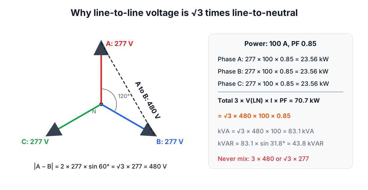
Each of the three phases delivers V(LN) × I × PF in a balanced load, so the total is P = 3 × V(LN) × I × PF. Substituting V(LN) = V(LL) ÷ √3 gives P = √3 × V(LL) × I × PF. Both forms are correct. The mistake is mixing them: using 480 V with the factor 3, or 277 V with √3. The first overstates power by 73%; the second understates it by 42%.
The same algebra holds for a delta-connected load. Each delta branch sees the full line voltage but carries a phase current that is the line current divided by √3, and three branches again sum to √3 × V(LL) × I(line) × PF. Because the formula uses line quantities, you never need to know whether the load inside the box is wired star or delta.
kW, kVA, kVAR and what each is for
| Quantity | Formula (three-phase) | Unit | Used for |
|---|---|---|---|
| Apparent power S | √3 × V(LL) × I | kVA | Transformers, generators, UPS, cables |
| Real power P | S × PF | kW | Energy bills, engine and turbine sizing, heating |
| Reactive power Q | S × sin(arccos PF) | kVAR | Capacitor banks, utility penalties |
Worked example: 100 A on a 480 V feeder at PF 0.85. S = 1.732 × 480 × 100 = 83.14 kVA. P = 83.14 × 0.85 = 70.67 kW. φ = arccos 0.85 = 31.8°, so Q = 83.14 × 0.527 = 43.8 kVAR. If you only knew the 70.67 kW and assumed unity power factor, you would calculate 85 A and undersize the feeder by 15%.
Going the other way, current from power: I = P ÷ (√3 × V × PF). A 15 kW load at 400 V and PF 0.85 draws 15,000 ÷ (1.732 × 400 × 0.85) = 25.5 A per line.
Motors: horsepower, efficiency and the NEC tables
A motor nameplate gives the mechanical output at the shaft. One horsepower is 745.7 W (NIST SP 811 defines the mechanical horsepower as 550 ft·lbf/s). The electrical input is the output divided by efficiency, and the current then follows from the power formula with the motor's power factor:
I = (hp × 745.7) ÷ (η × √3 × V × PF)
For a 10 hp motor at 460 V with 90% efficiency and PF 0.85: input = 7,457 ÷ 0.90 = 8,286 W, and I = 8,286 ÷ (1.732 × 460 × 0.85) = 12.2 A. The motor's nameplate full-load amps will be close to that.
The NEC, though, tells you to size motor conductors and short-circuit protection from Table 430.250 (three-phase) or 430.248 (single-phase), which gives 14 A for a 10 hp, 460 V motor. Those table values are deliberately conservative to cover motors of any make, speed and efficiency. Use the formula for energy estimates and generator loading; use the tables for wiring. Overload relays, by contrast, are set from the nameplate current.
Two traps with motors. First, efficiency and power factor both fall at light load: a 10 hp motor driving a 4 hp load may run at PF 0.6, so its current is higher than its kW suggests. Second, single-phase motors on 240 V draw about 1.73 times the current of a three-phase motor of the same power at the same voltage, because the √3 is missing.
Unbalanced loads and line-to-neutral circuits
The √3 formula assumes the same current in all three lines. In a building panel full of single-phase 120 V or 277 V circuits that is rarely true. The correct approach is to work per phase: add the VA connected between each line and neutral, and the largest phase total sets the feeder size. A panel with 18 kVA on phase A, 15 kVA on B and 12 kVA on C at 208Y/120 V has a phase A current of 18,000 ÷ 120 = 150 A, even though the balanced formula on the 45 kVA total would give 125 A.
Line-to-line single-phase loads (a 208 V water heater across two lines of a wye system) draw I = P ÷ (V(LL) × PF) from two lines and nothing from the third.
Common mistakes
- Using √3 with line-to-neutral voltage. If your voltage is 277 V, the multiplier is 3, not √3.
- Treating kW as kVA. At PF 0.8 that understates current by 25%.
- Forgetting efficiency on motors. Output horsepower is not input power.
- Applying the balanced formula to a lopsided panel. Size from the heaviest phase.
- Assuming 220, 230 and 240 V are the same. A 5% voltage difference is a 5% current difference.
When the formula is not enough
The power formula describes sinusoidal steady state. Non-linear loads such as variable frequency drives, rectifiers and LED drivers draw distorted current; then the "true" power factor includes a distortion term, RMS current is higher than the fundamental, and the neutral of a wye system can carry up to about 1.7 times the phase current from triplen harmonics. Motor starting, with locked-rotor currents of six to eight times running current, is a transient that needs its own check, as the generator sizing guide explains.
Next steps: the Power Factor Correction guide shows how to shrink the kVAR leg of the triangle, the transformer sizing guide turns kVA into a transformer rating, and the Wire Size Calculator turns the current into a conductor.