
How to Size Electrical Wire: Ampacity, Derating and Voltage Drop
Reading NEC Table 310.16 properly: terminal temperature limits, the 125% continuous-load rule, ambient and bundling derating, small-conductor breaker caps and when voltage drop decides the gauge.
· 11 min read
Choosing a wire size looks like a table lookup: find the amps, read across, done. In practice three separate limits apply, and the table is only one of them. The conductor must not overheat (ampacity), the breaker and lugs it lands on must not overheat (terminal temperature), and the load at the far end must still get enough voltage (voltage drop). This guide walks through each limit in the order an electrician or engineer checks them, using the same rules as the Wire Size Calculator. It explains the reasoning so you can follow a design or catch a mistake; the final decision belongs to your local code and a licensed electrician.
Why wire has an ampacity at all
Every conductor has resistance, so current turns some electrical energy into heat: P = I² × R per unit length. The heat flows out through the insulation into the surrounding air, conduit or soil. The wire settles at the temperature where heat in equals heat out. Ampacity is the current at which that steady temperature reaches the limit of the insulation: 60 °C for old TW and NM cable, 75 °C for THW and THWN, 90 °C for THHN, THWN-2 and XHHW-2.
That is why ampacity is not a property of copper alone. It depends on how well heat escapes (one cable in free air does better than nine in a conduit), on the starting temperature (a 45 °C attic leaves less room than a 30 °C basement), and on the insulation's limit. NEC Table 310.16 bakes in one standard situation: not more than three current-carrying conductors in a raceway, cable or earth, in 30 °C (86 °F) ambient. Everything else is a correction from there.
A few rows show the pattern. Copper 12 AWG is 20, 25 and 30 A in the 60, 75 and 90 °C columns. 8 AWG is 40, 50 and 55 A. 2 AWG is 95, 115 and 130 A. Aluminium is roughly two sizes behind copper for the same current, because its resistance is about 64% higher for the same size: 4/0 aluminium is 150, 180 and 205 A, close to 2/0 copper.
Step 1: the design current and the 125% rule
Start from the load current. For a motor, use the NEC full-load current tables (Article 430), not the nameplate; for an air conditioner use the minimum circuit ampacity on its label (Article 440). For everything else, use the calculated load.
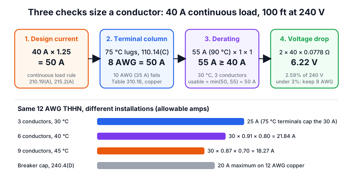
Then ask whether it is continuous, which the NEC defines as a maximum current expected to last three hours or more. EV chargers, water heaters, commercial lighting and heat tape all count. Sections 210.19(A)(1) and 215.2(A)(1) require the conductor, before any derating, to carry 125% of the continuous part plus 100% of the rest. The reason is the breaker: a standard thermal-magnetic breaker is tested to carry its rating in open air, and inside a loaded panel it can trip or run hot if held at 100% for hours. A 40 A continuous load therefore needs 50 A of conductor and a 50 A breaker.
Step 2: the terminal column
Here is the rule that catches people who learned from the table alone. Section 110.14(C) says the conductor's ampacity is limited by the lowest temperature rating of anything it connects to. Breakers and panel lugs are typically listed for 60 °C or 75 °C, not 90 °C. Unless the equipment is marked otherwise, circuits of 100 A or less, or conductors from 14 to 1 AWG, must use the 60 °C column; larger circuits use 75 °C. Most modern breakers are marked 60/75 °C, which lets you use 75 °C.
So THHN, a 90 °C wire, almost never gets its 90 °C ampacity on the final answer. It can, however, use the 90 °C value as the starting point for derating, which is where 90 °C insulation earns its keep. NM-B cable has 90 °C conductors but section 334.80 holds it to the 60 °C column outright.
Continuing the example: 50 A design current at 75 °C terminals points to 8 AWG copper, exactly 50 A. With 60 °C terminals, 8 AWG is only 40 A and you would need 6 AWG (55 A).
Step 3: correction for heat and crowding
Two factors reduce the table value for real installations.
Ambient temperature. Table 310.15(B)(1)(1) gives multipliers for each column. For 90 °C wire: 1.04 at 21 to 25 °C, 0.96 at 31 to 35 °C, 0.91 at 36 to 40 °C, 0.87 at 41 to 45 °C, 0.82 at 46 to 50 °C. For 60 °C wire the drop is steeper because there is less headroom between ambient and the insulation limit: 0.82 at 36 to 40 °C and only 0.58 at 46 to 50 °C. The factors come from the square-root relationship √((Tc − Ta) ÷ (Tc − 30)), because heat rejected is proportional to the temperature difference and heat generated to current squared.
More than three current-carrying conductors. Table 310.15(C)(1) applies 80% for 4 to 6, 70% for 7 to 9 and 50% for 10 to 20 conductors in one raceway or cable. Equipment grounding conductors never count. A neutral counts only when it carries more than unbalanced current, for example the neutral of a three-phase wye circuit feeding computers or LED drivers, where third harmonics add in the neutral.
Both factors multiply the 90 °C (or the insulation's own) ampacity, and the result must still be at least the actual load (not the 125% figure). Then the usable ampacity is the lesser of that adjusted value and the terminal-column value.
Take nine 12 AWG THHN conductors through a 45 °C attic: 30 A × 0.87 × 0.70 = 18.27 A. That still carries a 16 A load, and the terminal column (25 A at 75 °C) is higher, so 18.27 A is the ampacity. The same run in 14 AWG gives 25 × 0.87 × 0.70 = 15.23 A, too little for 16 A.
Step 4: the small-conductor breaker caps
Section 240.4(D) sets a ceiling on the overcurrent device for the smallest sizes no matter what the table says: 15 A on 14 AWG copper, 20 A on 12 AWG and 30 A on 10 AWG (15 A and 25 A for 12 and 10 AWG aluminium). The 25 A that 12 AWG shows at 75 °C is real and you use it for derating, but you still protect it at 20 A. Motor and air-conditioning circuits are exceptions under Articles 430 and 440, which have their own protection rules.
Step 5: voltage drop
Nothing so far depends on length. Voltage drop does. For DC and single-phase the drop is Vd = 2 × I × R × L, with R the resistance per unit length and L the one-way length; for balanced three-phase it is √3 × I × R × L. NEC Chapter 9 Table 8 gives 8 AWG stranded copper as 0.778 Ω per 1,000 ft at 75 °C, so 40 A over 100 ft drops 2 × 40 × 0.0778 = 6.22 V, or 2.59% at 240 V.
The NEC's informational notes suggest about 3% on a branch circuit or feeder and 5% overall. They are advice, not enforceable rules, but motors run hotter, lights dim and electronics misbehave when you ignore them. On long runs voltage drop, not ampacity, often decides the size. A 48 A EV charger needs 60 A of ampacity, which 6 AWG copper covers, and at 150 ft it still makes 2.95%; at 200 ft it would need 4 AWG. The Voltage Drop Calculator and our electronics basics guide cover the drop formula in more depth.
Metric cable and IEC 60364-5-52
Outside North America cable is sized in mm² under IEC 60364-5-52 or a national version such as BS 7671 or AS/NZS 3008. The structure is the same but the vocabulary differs. Design current Ib must not exceed the protective device rating In, which must not exceed the derated current-carrying capacity Iz. Iz = It × Ca × Cg, where It is the tabulated capacity for the installation method (A1, B1, C, E and so on), Ca the ambient factor and Cg the grouping factor. Typical copper PVC values for method C (clipped direct), two loaded conductors, are 19.5 A for 1.5 mm², 27 A for 2.5 mm², 36 A for 4 mm² and 46 A for 6 mm². A 32 A circuit passes on 4 mm², but over 25 m at 230 V it loses about 3.8%, so 6 mm² (2.56%) is the practical choice.
Common mistakes
- Using the 90 °C column for the answer. It is only the starting point for derating.
- Forgetting the 125% on continuous loads, especially EV chargers and water heaters.
- Counting the ground wire as current-carrying, or forgetting a harmonic-loaded neutral.
- Ignoring length. A size that passes ampacity can still give 6% drop on a long run.
- Sizing aluminium from the copper column. Use the aluminium values and listed AL-rated terminations.
- Sizing motors from the nameplate instead of the NEC full-load current tables.
When the simple model is not enough
The tables assume steady loads and standard conditions. Conductors buried in thermal insulation, run on rooftops in sunlight, installed in parallel, or carrying heavily non-linear loads need further rules (310.15(B)(2) for rooftops, 310.10(G) for parallel sets) or engineering supervision under 310.14(B) using the Neher-McGrath method. For anything beyond a straightforward branch circuit, have an engineer or licensed electrician do the design.
Related reading: The Three-Phase Power Formula for turning kW into amps, and Transformer Sizing for the feeders upstream. To turn a load into current first, use the Three-Phase Power Calculator.