
Orifice Flow Equation: Discharge Coefficient, Beta Ratio and ISO 5167
How a hole turns pressure into flow, what Cd and the vena contracta mean, the velocity of approach factor, sizing a restriction orifice and the limits of a fixed Cd.
· 10 min read

An orifice is about the simplest flow device there is: a plate with a hole in it. Put one in a pipe and the pressure difference across it tells you the flow. Choose the hole size and it limits the flow or burns off a set pressure. Drill one in a tank wall and it sets how fast the tank drains. This guide explains the equation behind the Orifice Flow Calculator: where it comes from, what the discharge coefficient and the vena contracta are, why the beta ratio adds a correction, how to size a restriction orifice, how much pressure is lost for good, and where a fixed coefficient stops being trustworthy.
From Bernoulli to the orifice equation
Take a pipe of diameter D with a thin plate whose hole has diameter d. Apply Bernoulli between the full pipe upstream (point 1) and the narrowest part of the jet just downstream of the plate (point 2), and use continuity to link the velocities. For an incompressible liquid with no losses:
Q_ideal = A₂ √( 2 ΔP / (ρ (1 − (A₂/A₁)²)) )
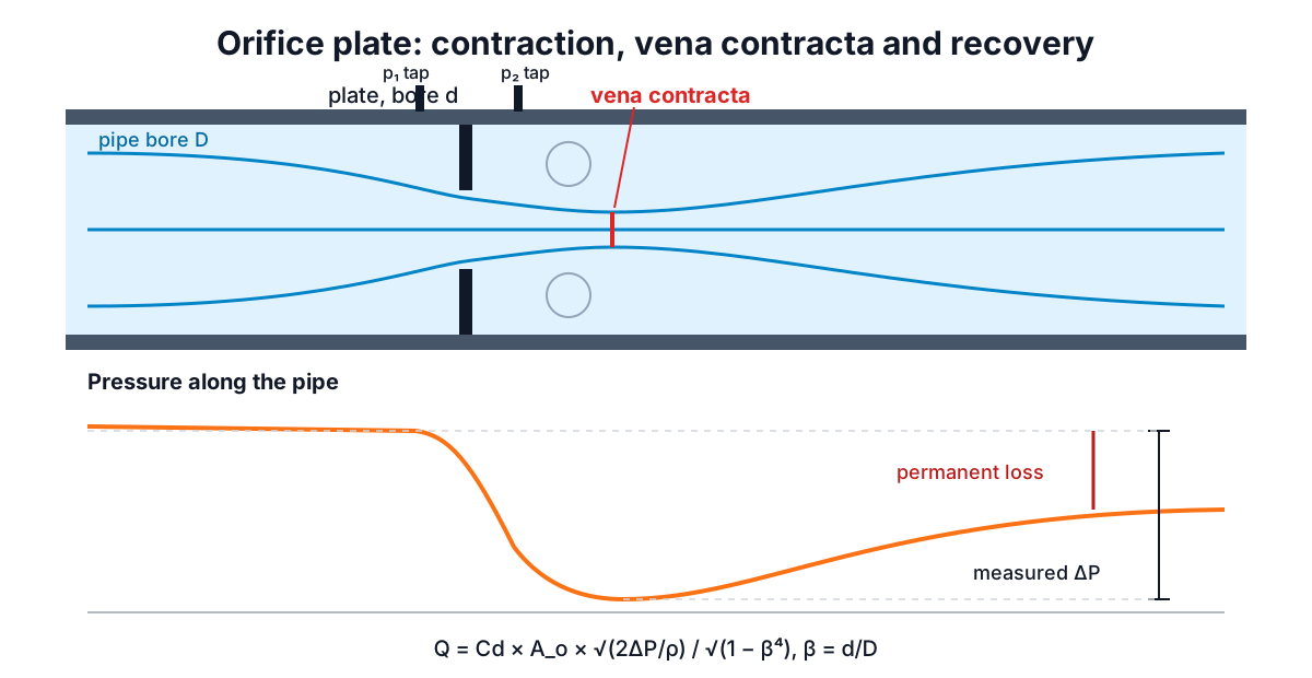
Two corrections turn this into the working equation. The jet keeps contracting after it leaves the hole, to a minimum section called the vena contracta about half a pipe diameter downstream, and some energy is lost. Both are lumped into a discharge coefficient Cd, and the hole area A_o is used instead of the unknown jet area:
Q = Cd × E × A_o × √(2 ΔP / ρ)
E = 1 / √(1 − β⁴),    β = d / D,    A_o = π d² / 4
E is the velocity of approach factor. It accounts for the fact that the liquid is already moving toward the plate in the pipe, carrying some kinetic energy with it. For a hole in the wall of a large tank, β is effectively zero and E = 1. ΔP is the differential pressure between the tappings; for a free orifice under a liquid head h, ΔP = ρgh and the equation becomes Q = Cd A_o √(2gh), which is Torricelli's law with a coefficient.
The discharge coefficient
For a sharp-edged orifice the jet area at the vena contracta is about 61 to 64% of the hole area, and the velocity is about 97 to 99% of ideal. Their product, Cd, is close to 0.61 at high Reynolds numbers, which is why that number appears in almost every handbook. Typical values for liquids:
| Device | Typical Cd |
|---|---|
| Sharp-edged orifice plate in a pipe | 0.60 to 0.62 |
| Sharp-edged hole in a tank wall | 0.60 to 0.64 |
| Short tube, length about 2 to 3 d | about 0.82 |
| Well-rounded (bell-mouth) inlet | 0.95 to 0.99 |
| ISA 1932 or long-radius flow nozzle | 0.96 to 0.99 |
| Classical Venturi tube | 0.984 to 0.995 |
The shape of the inlet edge is what matters. A sharp edge makes the jet separate and contract; a rounded entry lets it follow the wall, so nearly the whole area carries flow. A worn or rounded orifice plate therefore passes more flow than its nominal Cd predicts, and a meter using it reads low.
For accurate metering, ISO 5167-2 gives the Reader-Harris/Gallagher equation, which makes C a function of β, the Reynolds number in the pipe and the tapping arrangement (corner, flange or D and D/2 taps). It applies to plates with β from 0.1 to 0.75, pipe bores from 50 to 1000 mm and pipe Reynolds numbers above a few thousand, with specified straight lengths upstream. Inside those limits the standard quotes an uncertainty on C of roughly half a percent. Outside them, or with disturbed flow from a nearby elbow or valve, a fixed Cd of 0.61 can easily be several percent out. Part 3 of the standard covers nozzles and Part 4 Venturi tubes.
Worked example: flow from a measured ΔP
A 50 mm sharp-edged plate sits in a 100 mm water line (998.2 kg/m³). The differential gauge reads 25 kPa.
- β = 50/100 = 0.5, so E = 1/√(1 − 0.0625) = 1.0328.
- A_o = π × 0.05² / 4 = 0.0019635 m².
- √(2 × 25,000 / 998.2) = 7.077 m/s.
- Q = 0.61 × 1.0328 × 0.0019635 × 7.077 = 0.008755 m³/s = 8.75 L/s (31.5 m³/h).
Because Q goes with √ΔP, doubling the differential raises flow by only 41%, and a quarter of the full-scale differential means half the full-scale flow. Differential-pressure meters lose resolution at low flow for this reason; their usable turndown is often only about 3:1 or 4:1 with a single transmitter.
Swap the plate for a flow nozzle (Cd about 0.98) of the same bore and the same 25 kPa passes 14.1 L/s.
Worked example: sizing a restriction orifice
A bypass line needs to pass 20 m³/h of water while dropping 50 kPa, in an 80 mm pipe. Solve the equation for d. Because β depends on d, write x = d² and rearrange:
d² = Q / √( K² + Q² / D⁴ ), K = Cd (π/4) √(2ΔP/ρ)
With Q = 0.005556 m³/s, Cd = 0.61, ρ = 998.2 kg/m³ and D = 0.08 m, this gives d = 33.8 mm and β = 0.42. In practice you would round to a machinable size and check the actual flow. Two cautions apply to restriction orifices. If the downstream pressure is low, the pressure at the vena contracta can fall below the vapour pressure and the liquid cavitates, which erodes the plate and pipe and caps the flow. Large drops are often split across several plates in series for this reason. And for gas or steam, the flow chokes once the pressure ratio is low enough, so the liquid equation no longer applies.
Permanent pressure loss
The measured differential is not all lost. Downstream of the vena contracta the jet spreads out and part of the pressure recovers. ISO 5167-2 gives the permanent loss for an orifice plate as a fraction of the differential:
Δϖ / ΔP = (√(1 − β⁴(1 − C²)) − Cβ²) / (√(1 − β⁴(1 − C²)) + Cβ²)
At β = 0.5 and C = 0.61 that is 73% of ΔP; at β = 0.7 it is 51%. So in the first example about 18.3 kPa is lost for good. Flow nozzles lose less, and Venturi tubes, with their gentle diffuser, typically recover all but about 5 to 20% of the differential. That recovery is what you pay for with a Venturi: lower pumping cost on a large line in exchange for a longer and dearer meter.
Draining a tank through a hole
For a free orifice the driving head falls as the tank empties, so the flow falls too. For a vertical-sided tank of plan area A_t draining from depth H through a hole of area A_o, integrating Q = Cd A_o √(2gh) gives the time to empty:
t = (A_t / (Cd A_o)) × √(2H / g)
A 1 m diameter tank with 1.5 m of water and a 25 mm sharp-edged hole at the bottom (Cd 0.61) empties in about 1,450 s, roughly 24 minutes. Half that time empties three quarters of the contents, because the flow is fastest at the start. The Tank Volume Calculator gives the volume at each level, and the free-orifice mode of the calculator gives the flow at any head.
Common mistakes and limits
- Using the pipe area or the jet area instead of the hole area with Cd.
- Forgetting the approach factor at large β. At β = 0.7 it adds 15%.
- Measuring ΔP in the wrong place. Cd values belong to specific tapping positions.
- Applying a liquid equation to gas. Gas needs the expansibility factor ε from ISO 5167 and the upstream density, and it chokes at low pressure ratios.
- Low Reynolds numbers. With viscous liquids or tiny holes Cd changes markedly; check Re through the orifice with the Reynolds Number Calculator.
- Cavitation and flashing when the downstream pressure is close to the vapour pressure.
The orifice equation is Bernoulli plus a coefficient, so the Bernoulli guide is the place to see the ideal case. For the friction loss in the rest of the pipe, see Darcy-Weisbach and Colebrook.