
Bernoulli's Equation With Worked Examples: Heads, Venturis and Tanks
The energy balance behind p + ½ρv² + ρgz, the head form engineers draw, adding losses, three worked problems and the places where Bernoulli quietly stops applying.
· 10 min read

Bernoulli's equation is the first energy balance most engineers learn for moving fluids, and one of the most misused. It explains why water speeds up and loses pressure through a constriction, why a tank drains at the speed of a falling stone, and how a Venturi meter measures flow. It also has firm limits that are easy to forget. This guide works through the equation behind the Bernoulli Equation Calculator: where it comes from, the head form that engineers draw on drawings, how losses and continuity fit in, three worked problems, and the situations where it gives the wrong answer.
Where the equation comes from
Daniel Bernoulli published the idea in Hydrodynamica in 1738, and Leonhard Euler derived the modern form a few years later. Follow a small parcel of fluid along a stream line in steady flow. Newton's second law along that line, with no friction, integrates for an incompressible fluid to:
p + ½ ρ v² + ρ g z = constant
Each term is energy per unit volume (or pressure, in pascals):
- p is the static pressure, flow work.
- ½ρv² is kinetic energy per volume, the dynamic pressure.
- ρgz is potential energy per volume, from height z above a datum.
Between two points 1 and 2 on the same stream line:
p₁ + ½ρv₁² + ρgz₁ = p₂ + ½ρv₂² + ρgz₂
The trade is the whole idea. If the fluid speeds up, its pressure or height must fall to pay for it. If it climbs, it must lose pressure or speed.
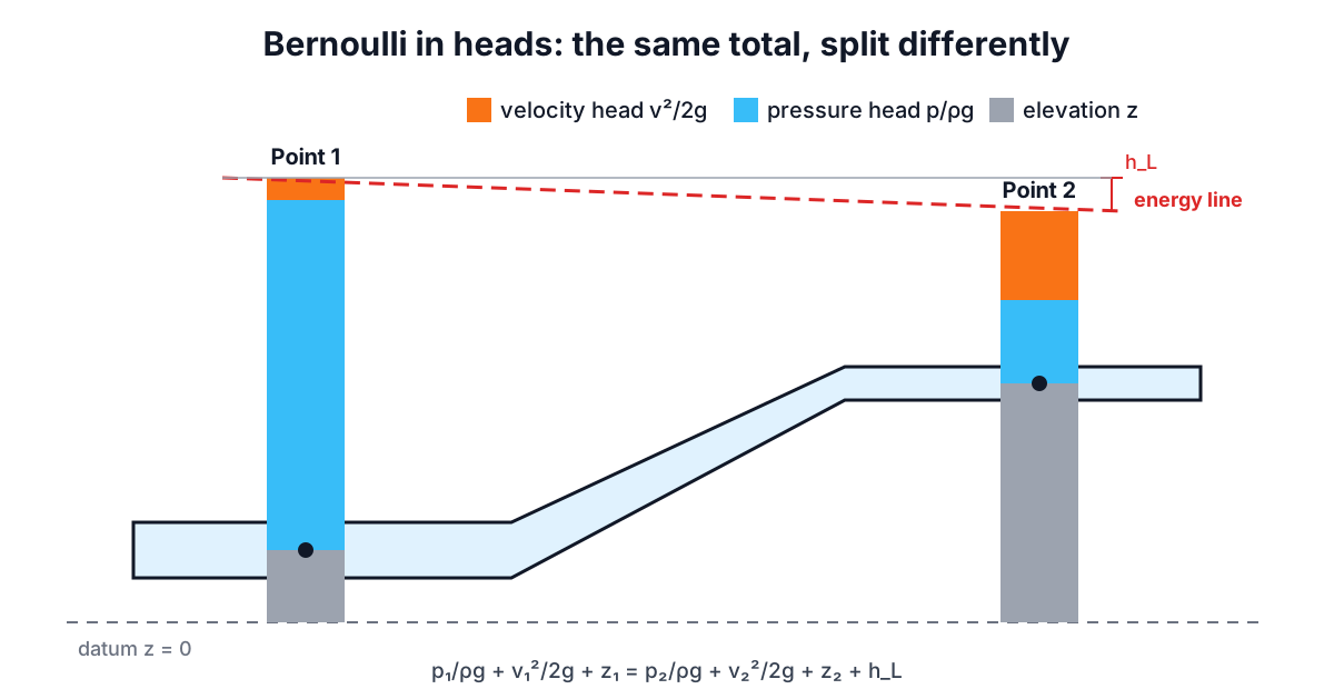
The head form and the energy grade line
Dividing every term by ρg turns energy into height, which is how hydraulic engineers think:
p/(ρg) + v²/(2g) + z = H (total head)
- Pressure head p/ρg: the height of liquid column the pressure could support.
- Velocity head v²/2g: the height the fluid would rise if all its speed turned into lift.
- Elevation head z.
Plot the total head along a pipeline and you get the energy grade line (EGL). Plot pressure head plus elevation and you get the hydraulic grade line (HGL), which sits one velocity head below the EGL and shows where a piezometer tube would fill to. Where the HGL drops below the pipe itself, the pressure is below atmospheric.
Real flow: adding head loss
Real fluids lose energy to friction and turbulence, which turns into heat. The engineering energy equation adds that loss on the downstream side, and any pump or turbine head in between:
p₁/ρg + v₁²/2g + z₁ + h_pump = p₂/ρg + v₂²/2g + z₂ + h_L + h_turbine
The calculator includes h_L directly. Take it from the Pipe Pressure Drop Calculator, which gives friction and fitting losses as head, then use Bernoulli to find what pressure is left. Do not put a pump between your two points without adding its head; Bernoulli alone says energy can only go down.
Continuity ties the velocities together
In a pipe, the two velocities are not independent. Mass conservation for an incompressible liquid gives:
Q = A₁ v₁ = A₂ v₂ v₂ = v₁ (D₁ / D₂)²
So if you know the flow and both diameters, you know both velocity heads, and Bernoulli gives the pressure change. That is what the calculator's pipe mode does. If instead you know both pressures, continuity and Bernoulli together give the flow:
Q = A₂ √[ 2 (p₁ − p₂ + ρg(z₁ − z₂ − h_L)) / (ρ (1 − (A₂/A₁)²)) ]
That is the ideal Venturi meter equation. Real meters multiply it by a discharge coefficient.
Worked example 1: water rising to an upper floor
Water enters a riser at 200 kPa gauge and 2 m/s. Five metres higher, the pipe has narrowed so the velocity is 4 m/s. What is the pressure there, ignoring losses (ρ = 1000 kg/m³)?
p₂ = p₁ + ½ρ(v₁² − v₂²) + ρg(z₁ − z₂)
   = 200,000 + 500 × (4 − 16) + 1000 × 9.80665 × (0 − 5)
   = 200,000 − 6,000 − 49,033
   = 144,967 Pa ≈ 145.0 kPa
The climb costs far more than the speed-up. Add a realistic 2 m of friction loss and p₂ drops by another 19.6 kPa, to about 125.4 kPa.
Worked example 2: a Venturi meter
A Venturi narrows from 100 mm to 50 mm, horizontal. Gauges read 150 kPa upstream and 120 kPa at the throat. Water at 1000 kg/m³.
- A₁ = 7,854 mm², A₂ = 1,963 mm², so (A₂/A₁)² = 1/16.
- Q = 0.001963 × √(2 × 30,000 / (1000 × 15/16)) = 0.001963 × 8.0 = 0.01571 m³/s.
The ideal flow is 15.71 L/s, with v₁ = 2.0 m/s and v₂ = 8.0 m/s. A classical Venturi tube has a discharge coefficient of about 0.98 to 0.995 under ISO 5167-4, so the real flow is a little less. Flip the problem round in the calculator's pipe mode: 10 L/s through the same contraction drops the pressure from 150 to 137.8 kPa.
Worked example 3: draining a tank and a siphon
Water drains through a small outlet 3 m below the surface of an open tank. Both the surface and the jet are at atmospheric pressure, and the surface velocity is negligible:
v₂ = √(2 g h) = √(2 × 9.80665 × 3) = 7.67 m/s
This is Torricelli's law (1643), Bernoulli a century early. A real sharp-edged hole delivers about 61% of the ideal flow because the jet contracts, which the Orifice Flow Calculator accounts for.
Now make it a siphon whose crest is 6 m above the tank surface, discharging 3 m below the surface. The velocity in the pipe is still 7.67 m/s (ignoring losses). At the crest:
p_crest = 0 − ½ρv² − ρg(6) = −29.4 − 58.8 = −88.3 kPa gauge
That is about 13 kPa absolute at sea level, uncomfortably close to the vapour pressure of warm water (7.4 kPa at 40 °C). Raise the crest a little more, or add friction, and the liquid boils at the top and the siphon breaks. Bernoulli tells you where the low-pressure point is; physics tells you the floor is the vapour pressure, not zero.
When Bernoulli does not apply
- Across pumps, fans and turbines without adding their head.
- With significant friction and no h_L term. Long pipes lose far more than the velocity heads involved.
- Across sudden expansions, valves and orifices without a loss term. A sudden expansion recovers only part of the velocity head as pressure; the rest becomes heat (the Borda-Carnot loss).
- For compressible flow. Gases with Mach numbers above roughly 0.3 (about 100 m/s in air) change density enough to matter.
- Unsteady flow such as water hammer or a rapidly closing valve.
- Between different stream lines in rotational flow, for example across a vortex.
Two more practical points. Use the same pressure reference at both points: gauge and gauge, or absolute and absolute. And use the mean velocity from continuity; strictly, the kinetic energy term needs a correction factor α of about 1.05 for turbulent and 2 for laminar flow, which matters only in laminar cases.
For the friction term, see Darcy-Weisbach and Colebrook. For flow through real holes and plates, see the orifice flow equation guide, and for the static case, where velocity is zero and Bernoulli collapses to p = ρgh, see hydrostatic pressure at depth.