
Power Factor Correction: Sizing Capacitors in kVAR and µF
What power factor is, why utilities charge for it, the tan φ formula behind every kVAR table, converting kVAR to microfarads for delta and star banks, and the harmonics trap.
· 10 min read

Power factor is the one electrical quantity that shows up on a utility bill without most people knowing what it is. A plant with lots of motors can pay a penalty for a low power factor, run its transformers hotter than its kW load justifies and lose more energy in its cables. A capacitor bank fixes all three, if it is sized correctly. This guide explains what power factor measures, derives the formula behind every capacitor selection table, converts kVAR into microfarads for the three ways a bank can be connected, and covers the cases where plain capacitors cause more trouble than they solve. The Power Factor Correction Calculator does the arithmetic.
What power factor measures
An induction motor needs a magnetic field to work, and building that field each half-cycle takes current that is 90° out of step with the voltage. That magnetising current flows back and forth between the supply and the motor without delivering energy, but it still travels through every cable, breaker and transformer on the way. Power factor is the share of the total current that does useful work:
PF = P ÷ S = kW ÷ kVA = cos φ
where φ is the angle between voltage and current. A heater has PF 1. A fully loaded induction motor is typically 0.8 to 0.9, and a lightly loaded one can fall to 0.5 or below. Fluorescent lighting with magnetic ballasts, welders and transformers running near no-load also pull the plant figure down.
The three powers form a right triangle. Real power P (kW) lies along the base, reactive power Q (kVAR) is the vertical side, and apparent power S (kVA) is the hypotenuse. For a given kW, a lower power factor means a taller triangle, a longer hypotenuse and more current. For background on how these quantities relate in a three-phase system, see the three-phase power formula.
Why utilities and engineers care
Current is what heats conductors and transformers. At PF 0.7 a load draws 1 ÷ 0.7 = 1.43 times the current it would at unity, so a transformer serving it is carrying 43% more current than the kW requires. Cable losses go with current squared, so they are about twice what they would be at unity. Voltage drop rises too.
Utilities see the same thing on their own network, which is why many commercial and industrial tariffs either bill demand in kVA rather than kW, or add a charge when the monthly power factor falls below a threshold, commonly 0.9 or 0.95. The exact rule varies by utility and country, so check your tariff before building a business case.
The capacitor formula
A capacitor draws current that leads the voltage by 90°, exactly opposite to the magnetising current. Put one in parallel with the load and its leading kVAR cancels part of the lagging kVAR. Real power stays the same, so the triangle keeps its base and only its height changes.
Before correction the reactive power is P × tan φ1. After, it is P × tan φ2. The capacitor must supply the difference:
Qc = P × (tan φ1 − tan φ2), where φ = arccos PF
Take a plant drawing 100 kW at PF 0.70 that wants to reach 0.95. tan(arccos 0.70) = 1.0202 and tan(arccos 0.95) = 0.3287, so Qc = 100 × 0.6915 = 69.15 kVAR. The bracketed number, 0.692, is the "multiplier" printed in the tables in capacitor catalogues, which list it for every combination of present and target power factor.
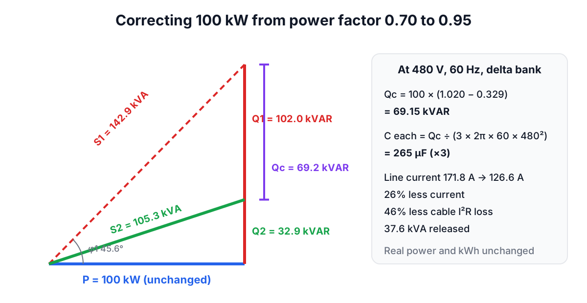
What the 69 kVAR buys: apparent power falls from 142.9 kVA to 105.3 kVA. Line current falls in proportion to PF1 ÷ PF2 = 0.70 ÷ 0.95, a 26% reduction; at 480 V three-phase that is 171.8 A down to 126.6 A. Cable losses upstream of the capacitors fall by 1 − (0.70 ÷ 0.95)² = 46%. The 37.6 kVA released can serve new load without a larger transformer.
From kVAR to microfarads
Capacitor banks are sold in kVAR at a rated voltage, but for single capacitors, motor capacitors and checking a bank with a meter you need capacitance. A capacitor C across voltage V at frequency f draws reactive power Q = V² × 2πf × C, so:
Single-phase: C = Q ÷ (2πf × V²)
Three-phase delta: each of three capacitors sits across the full line voltage and supplies a third of the total: C = Q ÷ (3 × 2πf × V(LL)²)
Three-phase star (wye): each capacitor sees V(LL) ÷ √3, and since Q scales with V², each must be three times larger than in delta: C = Q ÷ (2πf × V(LL)²)
For the 69.15 kVAR example at 480 V and 60 Hz in delta, each capacitor is 69,150 ÷ (3 × 377 × 480²) = 265 µF. In star it would be 796 µF but rated for only 277 V. Low-voltage banks are almost always delta because the capacitors are smaller; medium-voltage banks are often ungrounded star because it reduces the voltage each unit must withstand.
Rated voltage matters for another reason: a capacitor's kVAR output falls with the square of applied voltage. A 480 V, 50 kVAR unit on a 440 V system gives (440 ÷ 480)² × 50 = 42 kVAR.
Where to put the capacitors
- At individual motors. Correction switches with the motor and reduces current in the motor's own feeder. The capacitor must not exceed the motor's no-load magnetising kVAR, or the motor can self-excite and generate a dangerous voltage after it is disconnected. Motor makers publish maximum capacitor values; NEC 460.9 covers how the motor overload setting changes when a capacitor is on the load side.
- At the main switchboard, in automatic steps. A controller measures power factor and switches stages in and out as the load changes. This is the usual choice for a varied plant and avoids over-correction at night.
- At a group of loads, such as a motor control centre, as a compromise between the two.
The harmonics trap
Variable frequency drives, rectifiers, UPS units and LED drivers draw distorted current with harmonics at 5, 7, 11 and 13 times the fundamental. A capacitor's impedance falls as frequency rises, so capacitors attract harmonic current. Worse, a capacitor bank and the inductance of the supply transformer form a resonant circuit, with a resonant harmonic of roughly h = √(transformer kVA ÷ (capacitor kVAR × transformer impedance in per unit)). If that lands near the 5th or 7th harmonic, currents and voltages can be amplified enough to blow fuses and fail capacitors. Where non-linear loads exceed roughly 15 to 20% of the total, designers use detuned banks with series reactors (commonly tuned to about 189 Hz on a 50 Hz system, the "7%" detuning) or active filters. IEEE Std 519 sets harmonic limits at the point of common coupling; IEEE Std 18 and IEC 60831 cover the capacitors themselves.
Common mistakes
- Sizing from nameplate kW instead of measured demand. Motors rarely run at full load, and their power factor at part load is lower than the nameplate.
- Aiming for unity. Above about 0.98 the last few kVAR do little and risk a leading power factor at light load, which raises voltage and can upset standby generators.
- Ignoring the voltage rating. Using capacitors below their rated voltage gives fewer kVAR; above it shortens their life.
- Forgetting stored charge. Capacitors need discharge resistors and a waiting time before anyone touches them (NEC 460.6).
- Adding plain capacitors to a plant full of drives without a harmonic study.
Is it worth it?
The saving is in kVA demand charges, penalties and slightly lower losses, not in the kWh the motors use. Divide the annual reduction in charges by the installed cost of the bank to get a simple payback; one to three years is common where a penalty applies, and there may be no case at all where the tariff ignores power factor. Pair this with the Three-Phase Power Calculator to convert measured amps into kW and kVA, and the transformer sizing guide to see what the released kVA is worth.