
Transformer Sizing: kVA, Full-Load Amps and Standard Ratings
How to size a transformer from demand load, why ratings are in kVA, primary and secondary full-load current, turns ratio for delta-wye units, and the margins engineers add.
· 10 min read
Sizing a transformer is less about a formula than about deciding what load to design for. The arithmetic is two lines: convert the load to kVA, then divide by voltage to get current. The judgement is in what goes into the load figure, how much spare capacity to leave, and which of the standard ratings to buy. This guide covers both, with worked numbers you can reproduce in the Transformer Sizing Calculator. It is a design aid for preliminary sizing; protection, grounding and the final rating should be confirmed by a qualified engineer against your local code.
Why transformers are rated in kVA
A transformer's limit is temperature. Its losses are of two kinds: core losses, set by voltage and roughly constant whenever it is energised, and winding (copper) losses, set by current squared. Neither depends on whether the current is in phase with the voltage. A 75 kVA transformer carries the same current, and heats up the same, whether it feeds 75 kW of heaters at unity power factor or 60 kW of motors at 0.8. The manufacturer cannot know which, so the rating is apparent power in kVA.
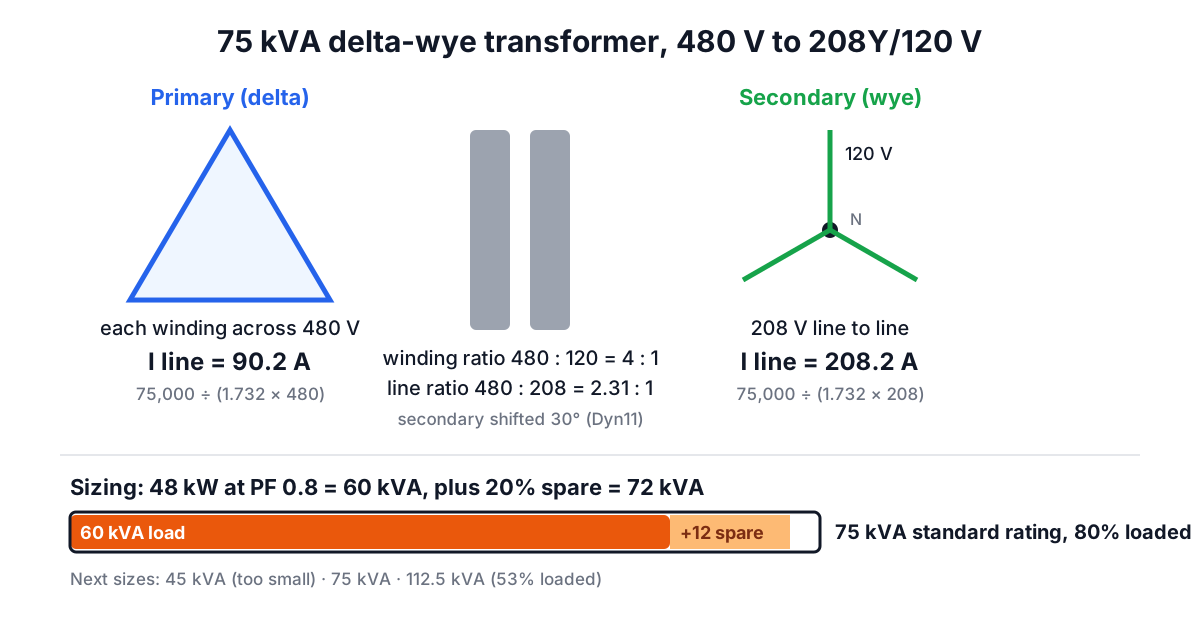
That has a practical consequence: always convert kW loads to kVA before sizing. 48 kW at PF 0.8 is 60 kVA. If you sized on 48 kVA you would undersize by 20%. The three-phase power guide explains the kW-kVA relationship in detail.
Full-load current
Rated current comes straight from the kVA:
- Single-phase: I = kVA × 1000 ÷ V
- Three-phase: I = kVA × 1000 ÷ (√3 × V(LL))
For a 75 kVA three-phase transformer stepping 480 V down to 208Y/120 V, primary current is 75,000 ÷ (1.732 × 480) = 90.2 A and secondary current is 75,000 ÷ (1.732 × 208) = 208.2 A. A 25 kVA single-phase unit with a 240 V secondary delivers 104.2 A.
These numbers feed everything downstream. NEC Table 450.3(B) bases primary and secondary overcurrent protection on them (for example, primary-only protection at 125% of primary current for transformers of 1,000 V and below, with next-size-up allowances), and section 240.21(C) has the rules for secondary conductors, which leave the transformer without protection at their source. The Wire Size Calculator turns those currents into conductor sizes.
Turns ratio and three-phase connections
For an ideal transformer the voltage ratio equals the turns ratio: a = Vp ÷ Vs = Np ÷ Ns, and current transforms the other way, Is = a × Ip. A 480 to 240 V single-phase unit has a = 2, so 52 A on the primary becomes 104 A on the secondary. Real transformers have a little leakage reactance and resistance, which is why secondary voltage sags slightly under load and why units are often wound a percent or two high or fitted with taps (commonly two 2.5% steps above and four below nominal on dry-type units).
Three-phase units add a twist. The ratio of line voltages is not always the ratio of winding turns. In the very common delta-wye connection, each primary winding sits across 480 V (line to line), while each secondary winding produces 120 V (line to neutral), so the winding ratio is 4:1 even though the line-to-line ratio is 480 ÷ 208 = 2.31:1. The delta-wye connection also shifts the secondary by 30°, which matters when paralleling transformers, and gives a neutral for 120 V or 277 V single-phase loads. The calculator reports the line-to-line ratio; check the nameplate vector group (for example Dyn11 in IEC notation) for the winding detail.
Deciding the load
The load figure is where good sizing is won or lost.
- Start from demand, not connected load. Adding every nameplate overstates the load because not everything runs at once. Use the code's demand factors (NEC Article 220 for buildings) or measured data. For an existing building, a month of logged kVA demand beats any estimate.
- Convert to kVA using a realistic power factor, or work in amps at the secondary voltage.
- Add spare capacity. Twenty to twenty-five percent is a common allowance for growth. It also means the unit runs at about 80% of its rating, which keeps temperature rise and winding losses moderate. The calculator applies this as a percentage on top of the load.
- Round up to a standard rating.
For 60 kVA of load with 20% spare: 72 kVA, rounded up to a standard 75 kVA, loaded to 80% today. For 18 kVA single-phase with 25% spare: 22.5 kVA, giving a 25 kVA unit at 72% load.
Standard ratings
North American liquid-filled and dry-type transformers come in a well-established sequence. Three-phase: 15, 30, 45, 75, 112.5, 150, 225, 300, 500, 750, 1000, 1500, 2000 and 2500 kVA, with small dry-type sizes of 3, 6 and 9 kVA. Single-phase: 1, 1.5, 2, 3, 5, 7.5, 10, 15, 25, 37.5, 50, 75, 100, 167, 250, 333 and 500 kVA. Pole-mounted utility units follow the single-phase list.
IEC markets use the R10 preferred-number series from IEC 60076: 25, 50, 63, 100, 160, 200, 250, 315, 400, 500, 630, 800, 1000, 1250, 1600, 2000, 2500 kVA. An 11 kV to 400 V substation serving 420 kVA with 20% spare needs 504 kVA, just over 500, so the next rating is 630 kVA at 67% load. Sometimes it is worth revisiting the margin rather than jumping a size: if 15% growth is enough, 483 kVA fits a 500 kVA unit at 84%.
When a bigger transformer is needed than the load suggests
- Motor starting. A large motor starting across the line draws six to eight times its running current. The transformer's impedance (typically 4 to 6% for distribution units) sets the resulting voltage dip. If the dip exceeds about 10 to 15%, lights flicker and contactors drop out. Either use a larger transformer (lower source impedance) or a soft starter or drive.
- Harmonics. Non-linear loads raise eddy-current losses in the windings. Use a K-factor rated transformer (K-4 or K-13 for office and IT loads) or derate a standard one per IEEE C57.110.
- High ambient or altitude. Ratings assume 30 °C average and 40 °C maximum ambient and altitudes up to 1,000 m (3,300 ft). Hot plant rooms and mountain sites need derating.
- Unbalanced single-phase loads on a three-phase unit. The most heavily loaded phase limits the transformer.
Common mistakes
- Sizing in kW. Always convert to kVA.
- Using connected load without demand factors, giving a transformer that runs at 30% and wastes core losses.
- Forgetting the secondary conductors. A 75 kVA, 208 V secondary needs conductors for 208 A, not the 90 A on the primary.
- Confusing line and winding ratios on delta-wye units when ordering a replacement.
- Ignoring future loads such as EV chargers or heat pumps that can each add 10 kVA or more.
Related tools and reading
Use the Three-Phase Power Calculator to turn a load schedule into kVA, the Power Factor Correction Calculator to see how much capacity correction would release (covered in the power factor guide), and the Generator Size Calculator if the same load needs standby power.