
Beam Deflection Formulas: Where 5wL⁴/384EI Comes From and When L/360 Applies
How the standard beam deflection formulas are derived, what E and I really control, which deflection limits the codes set, and the mistakes that make a beam bounce.
· 10 min read

A beam has two jobs. It must not break, and it must not move too much. The first is a strength check and usually gets all the attention; the second, deflection, is the one that decides the size of most floor joists, long-span steel beams and cantilevers. A beam that passes its stress check can still bounce underfoot, crack the plaster below or leave a door frame out of square. This guide explains where the standard deflection formulas come from, what controls the answer, which limits the codes apply, and the mistakes that show up again and again. All the numbers can be reproduced in the Beam Deflection Calculator.
Where the formulas come from
Every formula in a beam table is a solution of one differential equation. For a straight beam of linear-elastic material whose cross-sections stay plane, the curvature of the beam is proportional to the bending moment:
E I d²y/dx² = M(x)
E is the modulus of elasticity of the material, I the second moment of area of the section, y the deflection and M(x) the bending moment at position x. Integrate once and you have the slope; integrate twice and you have the deflection. The two constants of integration come from the supports: a pin or roller has zero deflection, a fixed end has zero deflection and zero slope.
Take a simply supported beam of span L with a uniform load w. The moment is M(x) = wx(L − x)/2. Integrating twice and applying y = 0 at both ends gives
y(x) = w x (L³ − 2 L x² + x³) / (24 E I)
which peaks at midspan at 5wL⁴/(384EI). The famous 5/384 is nothing more than this polynomial evaluated at x = L/2. The same procedure produces every other entry in the table:
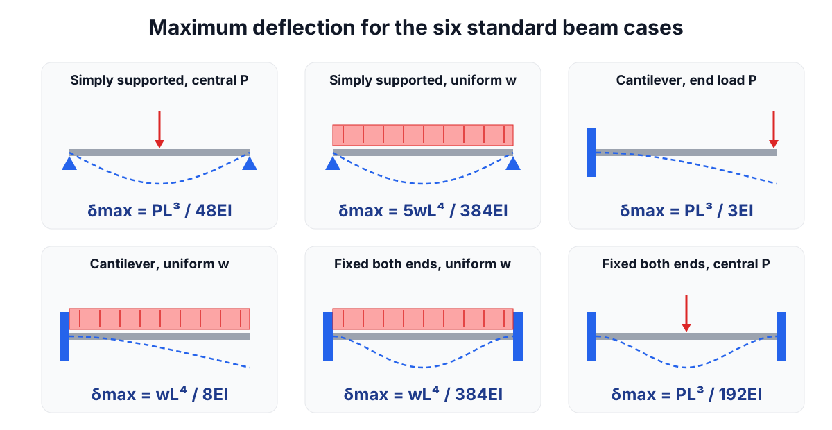
These are the expressions printed in the AISC Steel Construction Manual (Table 3-23, Shears, Moments and Deflections) and in Roark's Formulas for Stress and Strain. The off-centre point load is the one case with an awkward answer: with the load at distance a from the left support and b = L − a the shorter distance, the maximum deflection is Pb(L² − b²)^1.5 / (9√3 EIL) and it occurs at x = √((L² − b²)/3) from the far support. That location is never more than 0.077L from midspan, so the largest deflection is always between the load and the centre of the span, not under the load.
What actually controls deflection
Look at the formulas and three things stand out.
Span to the fourth power. For a distributed load, deflection grows with L⁴. A joist 10% longer deflects 46% more. This is why span tables jump a whole size for a small increase in span.
Stiffness E I in the denominator. E is a material property and I a geometric one. For structural steel E is close to 200 GPa (AISC uses 29,000 ksi) for every grade from S235 to S460, so a stronger steel does not deflect less. Aluminium alloys are about 69 GPa, a third of steel. Timber varies by grade: EN 338 gives a mean of 11 GPa for C24 and 8 GPa for C16, and the NDS Supplement lists 1,600,000 psi for Douglas fir-larch No.2 and 1,400,000 psi for spruce-pine-fir No.2.
Depth cubed inside I. For a rectangle I = bh³/12. Doubling the depth multiplies I by eight; doubling the width only doubles it. Turning a plank from flat to on edge is the cheapest stiffness you will ever buy. The Section Properties Calculator gives I for rectangles, tubes, I-beams, tees, channels and angles.
End restraint matters too. Fixing both ends of a uniformly loaded beam cuts the deflection to a fifth of the simply supported value, and fixing both ends under a central point load cuts it to a quarter. A cantilever goes the other way: with an end load it deflects PL³/3EI, sixteen times a simply supported beam of the same span with a central load.
Deflection limits in the codes
Deflection limits are serviceability criteria. They protect finishes, keep floors from feeling lively and keep water from ponding, rather than preventing collapse. The International Building Code, Table 1604.3, sets the most quoted values:
| Member | Live load | Dead + live |
|---|---|---|
| Floor members | L/360 | L/240 |
| Roof, supporting plaster or stucco ceiling | L/360 | L/240 |
| Roof, supporting non-plaster ceiling | L/240 | L/180 |
| Roof, no ceiling | L/180 | L/120 |
For cantilevers, footnote h of that table takes L as twice the cantilever length, which doubles the allowance. Eurocode 0 leaves limits to the national annex; L/250 under quasi-permanent load and L/300 to L/500 where brittle partitions are present are common. Manufacturers of stone and tile floors often ask for L/720 or better, because tile cracks long before a floor feels bouncy.
The Beam Deflection Calculator checks L/180, L/240 and L/360 at once and shows the utilisation, so you can see how much margin a section has.
A worked example
A 47 x 150 mm C24 joist spans 3.6 m and carries 1.5 kN/m of floor load. The section has I = 47 x 150³ / 12 = 13.2 x 10⁶ mm⁴ (1,322 cm⁴). With E = 11 GPa:
δ = 5 x 1.5 N/mm x 3600⁴ mm⁴ / (384 x 11000 N/mm² x 13.22e6 mm⁴)
  = 22.6 mm  =  L / 160
The L/360 allowance is 10 mm, so the joist fails by a wide margin. The fix is depth, not width: a 47 x 200 mm joist has (200/150)³ = 2.37 times the I and deflects 9.5 mm, just inside the limit. Going to 75 x 150 mm instead would only raise I by 60% and still fail.
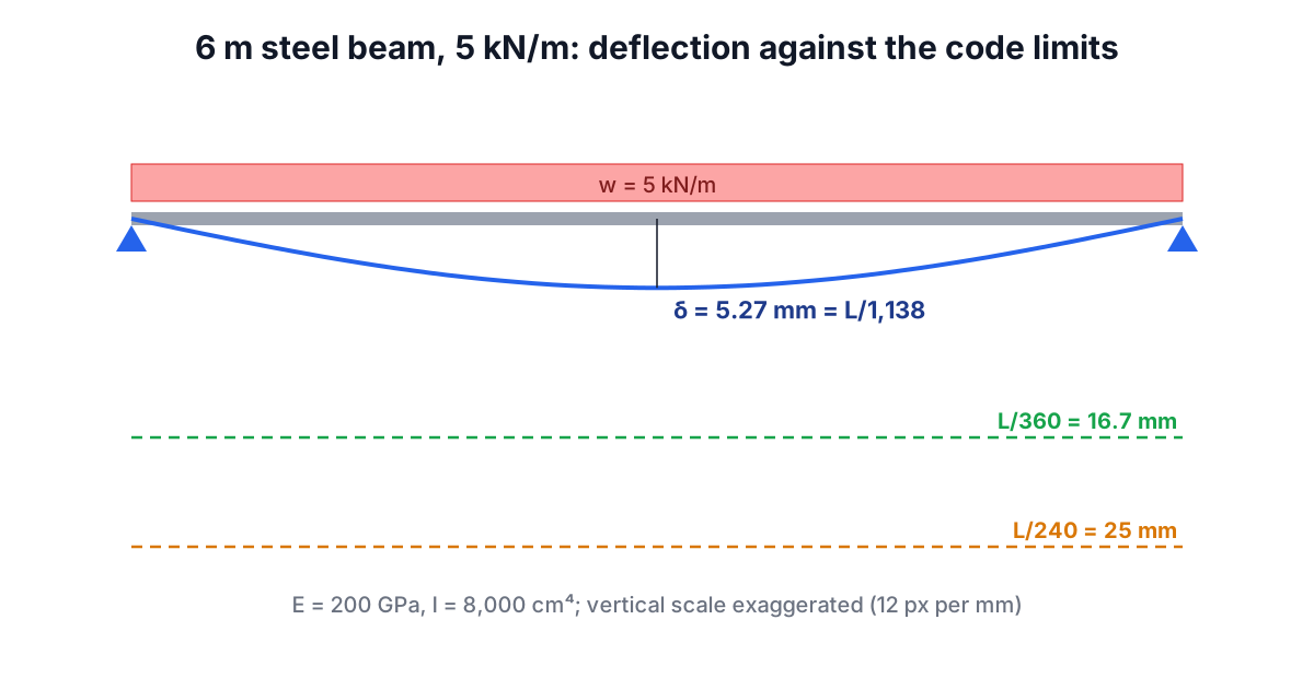
A steel example for contrast: a beam with I = 8,000 cm⁴ spanning 6 m under 5 kN/m deflects 5.27 mm, or L/1,138, with a maximum moment of 22.5 kN·m and end slopes of 0.0028 rad. That beam is governed by strength or vibration long before deflection becomes a problem.
Mistakes that give the wrong answer
Mixed units. The formulas only work in a consistent set. The classic error is load in kN/m, span in metres and I in cm⁴ dropped straight into 5wL⁴/384EI. Convert everything to N and mm (w in N/mm equals kN/m, E in N/mm² equals MPa, I in mm⁴) or to pounds and inches. The calculator does this for you, but a hand check should too.
Wrong axis. I must be about the axis the beam bends about. Steel tables list Ix (strong axis) and Iy (weak axis); a W-shape used flat has perhaps a tenth of the stiffness.
Leaving out self-weight and dead load. The L/360 check is usually for live load alone, but the L/240 check is for everything, including the weight of the beam, the floor deck and the ceiling.
Ignoring creep. Timber and concrete keep deflecting under sustained load. Eurocode 5 multiplies the long-term part by (1 + kdef), about 1.6 for solid timber in a heated building, and the NDS uses a creep factor of 1.5 for seasoned lumber. Concrete beams crack, which lowers the effective I well below the gross value.
Trusting fixed ends. A beam bolted to columns is rarely fully fixed. Unless the connection is designed as moment-resisting, check the simply supported case as well.
When the simple model breaks down
The standard formulas assume small deflections, a prismatic member, elastic material and negligible shear deformation. Shear deformation adds noticeably to deflection in short deep beams (span under about ten times depth), in plywood and LVL I-joists with thin webs, and in sandwich panels. Tapered beams, notched joists and beams with large holes need the stiffness integrated along the length. Very slender members such as cables and thin strips enter large-deflection behaviour, where the beam formulas over-predict the movement.
Loads that combine several standard cases can simply be added, because the theory is linear: a beam carrying a uniform load and a point load deflects by the sum of the two separate results. For arbitrary patterns of loads, the Shear and Bending Moment Calculator gives the moment diagram that the deflection integral starts from, and the guide to shear force and bending moment diagrams explains how to build it by hand. When the member is in compression rather than bending, read the column buckling guide instead, and for getting I right in the first place, see the guide to moment of inertia and section modulus.
These calculations are for preliminary sizing and checking. Members that carry people or property should be designed or reviewed by a qualified engineer against the governing code.