
Moment of Inertia, Section Modulus and Radius of Gyration for Engineers
What each section property means, how to calculate centroids and the parallel axis theorem by hand, elastic versus plastic modulus, and the unit traps.
· 10 min read

Two beams made of the same steel and weighing the same per metre can differ in stiffness by a factor of ten. The difference is entirely in the shape of the cross-section, and it is captured by a handful of numbers called section properties: area, centroid, second moment of area, section modulus, plastic modulus and radius of gyration. This guide explains what each one means physically, how to calculate them by hand for built-up shapes, and where the common unit and axis mistakes come from. The Section Properties Calculator does the arithmetic for eight standard shapes.
Area and centroid
The area A is the easy one. It sets the axial stress under tension or compression (σ = P/A) and the weight per length. The centroid is the geometric centre of the area, the point where the section would balance on a pin. For a shape made of simple pieces, take the first moment of each piece about a reference line, add them, and divide by the total area:
ȳ = Σ (Aᵢ yᵢ) / Σ Aᵢ
Consider a T-section with a 150 x 12 mm flange on top of an 8 mm thick stem, 150 mm deep overall. The stem is 8 x 138 = 1,104 mm² with its centroid 69 mm above the bottom; the flange is 150 x 12 = 1,800 mm² at 144 mm. So
ȳ = (1,104 x 69 + 1,800 x 144) / 2,904 = 115.5 mm from the bottom of the stem
Bending happens about the centroidal axis, so every other property depends on getting this right.
Second moment of area
The second moment of area I, often called the area moment of inertia, measures how far the material lies from the bending axis. Each small piece of area contributes its area times the square of its distance from the axis:
I = ∫ y² dA
For a rectangle about its own centroid this gives the formula every engineer knows, I = bh³/12. The cube is the key fact of structural design: doubling depth multiplies I by eight. For a solid circle I = πD⁴/64, and for a tube you subtract the hole.
Built-up shapes use the parallel axis theorem. A piece whose own centroid is a distance d from the overall centroid contributes its own I plus its area times d²:
I = Σ ( Iᵢ + Aᵢ dᵢ² )
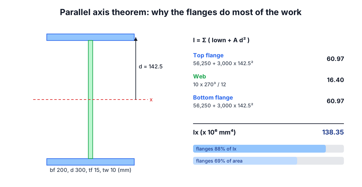
Take an I-beam 300 mm deep with 200 x 15 mm flanges and a 10 mm web. Each flange has its own I of 200 x 15³/12 = 56,250 mm⁴, tiny, but sits 142.5 mm from the axis, contributing 3,000 x 142.5² = 60.9 x 10⁶ mm⁴. The web adds 10 x 270³/12 = 16.4 x 10⁶ mm⁴. The total is 138.35 x 10⁶ mm⁴, and the flanges provide 88% of it with 69% of the area. That is why I-beams exist: put the material where the d² term rewards it.
I governs stiffness: deflection is inversely proportional to EI, and the Euler buckling load is proportional to it. The beam deflection formulas guide and the column buckling guide both start from this number.
Elastic section modulus
Bending stress grows linearly from zero at the neutral axis to a maximum at the fibre farthest away, a distance c from the centroid:
σmax = M c / I = M / S with S = I / c
S is the elastic section modulus, and it converts a bending moment directly into the peak stress. For a rectangle S = bh²/6. For the I-beam above, c = 150 mm and S = 922,350 mm³.
Unsymmetrical sections have two values. The T-section's centroid is 115.5 mm from the stem tip but only 34.5 mm from the top of the flange, so S at the top is 162,900 mm³ and at the stem tip only 48,700 mm³. The stem tip sees more than three times the flange stress, and the design must use the smaller S. A common error is to compute I correctly and then divide by half the depth.
Plastic section modulus and shape factor
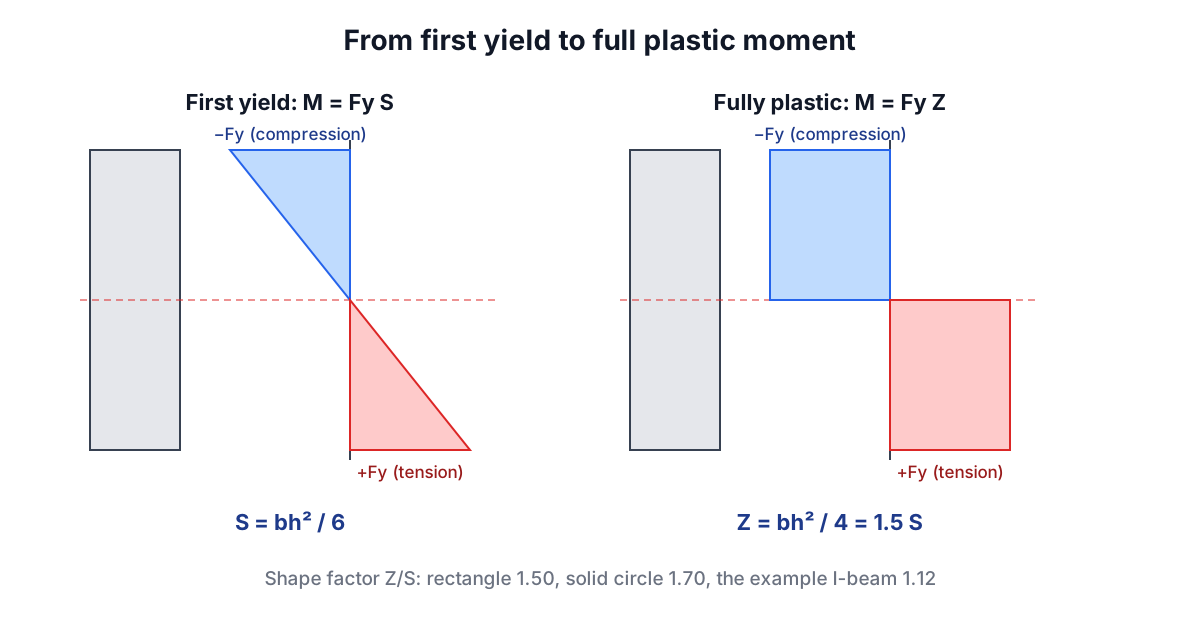
Steel does not fail when the extreme fibre first yields. Keep increasing the moment and yielding spreads inward until the whole section is at the yield stress, half in tension and half in compression. The axis that divides those halves, the plastic neutral axis, splits the area into two equal parts, which for an unsymmetrical shape is not the centroid. The resisting moment is then Fy times the plastic modulus:
Z = A_top x ȳ_top + A_bottom x ȳ_bottom     (each half's area times its centroid distance from the plastic axis)
Mp = Fy Z
For a rectangle Z = bh²/4, 1.5 times S. For a solid circle Z = D³/6, 1.70 times S. For the I-beam Z = 1,037,250 mm³, only 1.12 times S, because the flanges were already working hard at first yield. This ratio is the shape factor. AISC 360 uses Z for compact beams (Mn = Fy Zx), and Eurocode 3 uses Wpl for class 1 and 2 sections, which is the same quantity under another name.
Radius of gyration and principal axes
The radius of gyration r = √(I/A) is the distance at which the whole area, concentrated in a thin strip, would give the same I. It carries no new information but packages stiffness per unit area, which is what column design needs: the slenderness ratio is KL/r. A tube has a large r for its area, which is why round and square hollow sections make efficient columns.
For angles and other sections without an axis of symmetry, the axes of maximum and minimum I are not the leg directions. The product of inertia Ixy = Σ Aᵢ dxᵢ dyᵢ is not zero, and Mohr's circle gives the principal values:
I_max, I_min = (Ix + Iy)/2 ± √( ((Ix − Iy)/2)² + Ixy² )
For an equal angle the principal axes are at 45 degrees. A 100 x 75 x 8 mm unequal angle has rx = 22.2 mm and ry = 31.8 mm but a minimum r of only 16.2 mm about an inclined axis, and that minimum governs a single-angle strut.
Units and other traps
Powers of ten. I has units of length to the fourth power. 1 cm⁴ = 10⁴ mm⁴, 1 m⁴ = 10¹² mm⁴, and 1 in⁴ = 41.62 cm⁴ = 416,231 mm⁴. European tables list I in cm⁴ and S in cm³; US tables use in⁴ and in³; many design calculations work in mm⁴ written as "x 10⁶". The Section Properties Calculator shows two units side by side for this reason.
Moment of inertia of mass. Dynamics uses a mass moment of inertia, in kg·m², for rotating bodies. It is a different quantity that happens to share the name.
Fillets and radii. Rolled sections have root fillets and rounded toes. An L4x4x1/2 angle calculated with sharp corners gives A = 3.75 in² and ȳ = 1.18 in, matching the AISC Manual, and Ix = 5.56 in⁴ against the tabulated 5.52 in⁴. For rolled shapes use the published tables; for plate girders and fabricated sections, the sharp-corner calculation is the right one.
Polar moment and torsion. J = Ix + Iy is the torsion constant only for circles and tubes. For open sections such as I-beams and channels the torsion constant is far smaller, roughly Σ bt³/3, which is why open sections are poor at resisting twist.
Section properties feed every other structural check. The Shear and Bending Moment Calculator gives the moment to divide by S, the Beam Deflection Calculator and the Column Buckling Calculator use I and r, and the steel weight formulas guide turns the same area into kilograms per metre. Final member design should be checked by a qualified engineer against the governing code.