
Column Buckling Explained: Euler, K Factors, Slenderness and the Johnson Parabola
Why slender columns fail below yield, how effective length factors work, where Euler stops being valid, and how the AISC column curve compares.
· 11 min read

Push on the ends of a plastic ruler and it does not crush. It bows sideways at a surprisingly small force, and once it has bowed it will not take any more. That is buckling, and it is the reason a slender steel column can fail at a stress far below the yield strength printed on the mill certificate. This guide explains the Euler formula and where it comes from, how effective length factors capture end conditions, why the formula stops working for stocky columns, and how the Johnson parabola and modern code curves take over. The numbers come from the Column Buckling Calculator.
Euler's critical load
Leonhard Euler solved the problem in 1744. Consider a perfectly straight, pin-ended column of length L carrying an axial load P exactly through its centroid. If it deflects sideways by a small amount y, the load acting through that offset produces a bending moment M = −Py. Combining that with the beam curvature equation E I y'' = M gives
E I y'' + P y = 0
whose solutions are sine waves. The only one that satisfies y = 0 at both pinned ends with a non-zero deflection needs P to take a particular value:
Pcr = π² E I / L²
Below Pcr, any sideways disturbance dies away. At Pcr the straight column is in neutral equilibrium and can sit in a bent shape; the smallest imperfection then grows without limit. Three things stand out: the load depends on stiffness E I rather than strength, it falls with the square of length, and the I that matters is the smallest one, because the column buckles about its weakest axis.
Effective length and the K factor
Real columns are not all pinned. Fixing an end against rotation changes the shape of the buckled wave, and the trick that handles every case is the effective length KL: the distance between points of inflection (zero moment) in the buckled shape. Replace L with KL and the Euler formula covers any end condition:
Pcr = π² E I / (K L)²
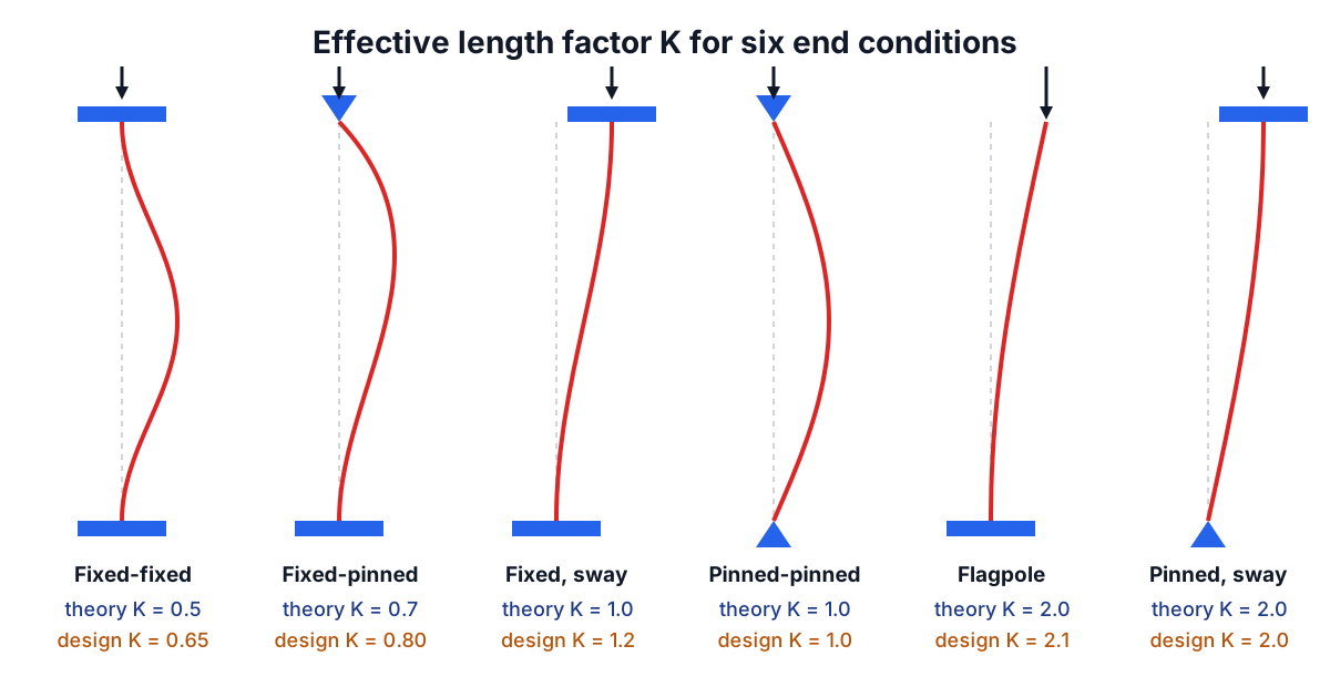
The theoretical values are 0.5 for both ends fixed, 0.7 for one fixed and one pinned, 1.0 for both pinned, and 2.0 for a flagpole fixed at the base and free at the top. Because the load varies with 1/K², the flagpole carries one sixteenth of the load of the same column fixed at both ends.
Perfect fixity does not exist. A "fixed" base plate rotates a little on its anchor bolts and the concrete beneath, and a welded beam-to-column joint has some flexibility. The AISC Specification commentary (Table C-A-7.1) therefore recommends design values of 0.65, 0.80, 1.2, 1.0, 2.1 and 2.0 for the six standard cases. The calculator lets you choose between them; for real connections, the design values are the safer choice. In frames where the columns can sway, K depends on the stiffness of the beams framing in and comes from alignment charts or a second-order analysis, and is often well above 1.0.
Slenderness ratio and radius of gyration
Dividing Pcr by the area gives the critical stress:
σcr = π² E / (K L / r)² where r = √(I / A)
The radius of gyration r combines the section's size and shape into one length, and the slenderness ratio KL/r is the single number that decides how prone a column is to buckling. Steel building columns usually fall between 40 and 120. AISC recommends keeping KL/r below 200 for members in compression, because very slender members are easily damaged and vibrate.
For a pinned 3 m steel tube 100 mm in diameter with a 5 mm wall, I = 1.688 x 10⁶ mm⁴ and A = 1,492 mm², so r = 33.6 mm and KL/r = 89.2. The Euler load is π² x 200,000 x 1.688 x 10⁶ / 3,000² = 370 kN, a stress of 248 MPa.
When Euler stops working
Euler assumes the material stays elastic all the way to buckling. For a slender column the critical stress is small and that holds. As the column gets shorter, Euler's stress rises without limit, and at some point it predicts a buckling stress above yield, which is impossible. Long before that, a real column runs into trouble because of residual stresses: rolled and welded sections cool unevenly, leaving parts of the cross-section already stressed to perhaps 30 to 50% of yield before any load is applied. Those parts yield early, the effective stiffness drops, and buckling happens below the Euler value.
The classic dividing line, used in the old AISC allowable stress specification and in most machine design texts, is half the yield stress. The slenderness at which the Euler stress equals Fy/2 is
Cc = √(2 π² E / Fy)
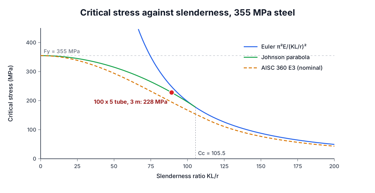
which is about 126 for 36 ksi (250 MPa) steel and 105 for 355 MPa steel. Above Cc the column is slender and Euler applies. Below Cc it is intermediate, and J. B. Johnson's parabola takes over:
σcr = Fy − (Fy² / (4 π² E)) (K L / r)²
The parabola starts at Fy for a column of zero length and meets the Euler curve tangentially at Cc. Our tube, at KL/r = 89.2 with Fy = 355 MPa, is below Cc = 105.5, so the Johnson stress of 228 MPa (340 kN) governs. Euler alone would overstate the capacity by about 9%.
What the design codes do
Euler and Johnson describe ideal columns. Real ones are slightly crooked (the AISC Code of Standard Practice allows L/1000), the load is never exactly central and residual stresses vary by section type. Modern codes therefore fit curves to large test programmes. AISC 360-16 Section E3 uses
Fe  = π² E / (K L / r)²
Fcr = 0.658^(Fy/Fe) x Fy       when K L / r <= 4.71 √(E / Fy)
Fcr = 0.877 x Fe                otherwise
with φ = 0.90 for LRFD or Ω = 1.67 for ASD. For the same tube the code gives Fcr = 195 MPa and φPn = 262 kN, about 70% of the Euler load. Eurocode 3 uses a family of five curves (a0 to d) chosen by section type, which capture the different residual stress patterns of hot-finished tubes, rolled I-sections and welded boxes.
A useful US example is a 4 in Schedule 40 pipe column (I = 7.23 in⁴, A = 3.17 in²) 10 ft long with pinned ends in 35 ksi steel. KL/r = 79.5, the Euler load is 144 kips, the Johnson load 89.5 kips and the AISC LRFD strength 72.3 kips. Make the same pipe a 20 ft flagpole with K = 2.1 and KL/r jumps to 334, beyond the recommended limit, with an Euler load of only 8.1 kips.
Common mistakes
Using the strong-axis I. An I-beam used as a column buckles about its weak axis unless that axis is braced. For a typical W-shape the weak-axis I is a third to a tenth of the strong-axis value.
Forgetting bracing changes L, not K. A brace at mid-height halves the unbraced length about the braced axis and quadruples the Euler load about that axis. Check both axes with their own lengths.
Treating Euler as a safe design value. It is an upper bound for a perfect column. Divide by a factor of safety, or better, use the code curve.
Ignoring local buckling. Thin-walled tubes and plates can wrinkle locally before the whole column buckles. AISC limits D/t for round tubes to 0.11E/Fy for the full-strength column equations, and slender elements need the reduced effective area of Section E7.
Using Euler for timber and concrete. Wood columns are designed with the Ylinen equation in NDS 3.7 or the Eurocode 5 instability factors, and concrete columns with the ACI 318 slenderness and moment magnification rules.
Related reading
Buckling depends on the minimum second moment of area and the radius of gyration, which the Section Properties Calculator works out, with background in the guide to moment of inertia and section modulus. Beams that load the column are covered by the beam deflection formulas guide and the shear force and bending moment diagram guide, and the Steel Weight Calculator gives the self-weight of the members.
Buckling calculations here are for preliminary sizing. Columns support everything above them, so final designs must be checked by a qualified engineer against the governing code.