
Reading Capacitor Codes: 104, 2A104J, X7R and C0G Explained
How three-digit capacitor codes work, what tolerance letters and EIA voltage codes mean, and why the dielectric code matters as much as the value.
· 9 min read

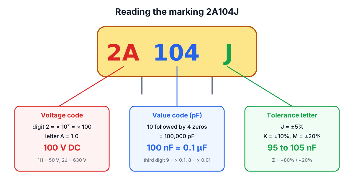
A ceramic disc capacitor a few millimetres across has room for three or four characters at most, so "100 nF, 100 V, ±5%" becomes 2A104J. Once you know the scheme, those characters carry a surprising amount of information. This post explains each part of the marking: the three-digit value code, the R notation for tiny values, tolerance letters, the EIA voltage code, and the dielectric code (X7R, C0G and friends) that tells you how much the capacitance will actually drift. Every example can be decoded in the Capacitor Code Calculator.
Picofarads, nanofarads and microfarads
All capacitor codes resolve to picofarads, so the unit ladder is the first thing to have straight:
- 1 µF = 1,000 nF = 1,000,000 pF
- 1 nF = 1,000 pF = 0.001 µF
- 1 pF = 0.001 nF
Older American schematics often skip nanofarads entirely, writing 0.1 µF or 0.0047 µF ("mfd"), and some use "mmfd" or "µµF" for picofarads. European schematics often write values as 4n7 or 100n, with the prefix letter replacing the decimal point. The same capacitor, 104, is 0.1 µF, 100 nF or 100,000 pF depending on who drew the diagram.
The three-digit value code
The value code works just like resistor colour bands, written in digits:
- The first two digits are significant figures.
- The third digit is the number of zeros to add.
- The result is in picofarads.
So 104 is 10 followed by 0000, which is 100,000 pF or 100 nF. 472 is 4,700 pF (4.7 nF), 223 is 22 nF, 101 is 100 pF and 105 is 1 µF. A third digit of 0 means no zeros: 100 is 10 pF, not 100 pF, which catches people out.
Two extra multipliers cover fractional picofarads. A third digit of 9 means multiply by 0.1, and 8 means multiply by 0.01. 229 is 2.2 pF and 478 is 0.47 pF. The digit 7 is not used, and 6 (as in 106, 10 µF) appears mostly on tantalum and larger ceramic parts.
Small values often use R as the decimal point instead: 4R7 is 4.7 pF and R47 is 0.47 pF. A plain one- or two-digit number such as 47 or 22 is read directly in picofarads, common on small ceramic discs.
Because the code holds only two significant figures, it matches the E6, E12 and E24 preferred-value series that capacitors are made in. Ceramic capacitors are most often stocked in E6 or E12 steps (1.0, 1.5, 2.2, 3.3, 4.7, 6.8, plus 1.2, 1.8, 2.7, 3.9, 5.6, 8.2), since their tolerance is wide enough that finer steps add little.
Tolerance letters
A letter after the value is the tolerance, using the letter code standardised in IEC 60062:
| Letter | Tolerance | Typical use |
|---|---|---|
| B, C, D | ±0.1, ±0.25, ±0.5 pF | Values below 10 pF, where a percentage would be tiny |
| F, G | ±1%, ±2% | Precision C0G and film parts |
| J | ±5% | Film capacitors, C0G ceramics |
| K | ±10% | Most X7R and X5R ceramics |
| M | ±20% | General-purpose ceramics, electrolytics |
| Z | +80% / −20% | Old Y5V and Z5U decoupling parts |
Z deserves a comment. A "100 nF" Z-tolerance part can legitimately measure anywhere from 80 nF to 180 nF when new, before temperature and voltage effects are counted. That was acceptable for supply decoupling, where more capacitance is never a problem, and it is why such parts should not go anywhere the value matters.
EIA voltage codes
When a voltage rating is printed as a code, it is two characters: a digit and a letter. The digit is a power of ten and the letter is a mantissa from a fixed table:
| Letter | A | C | E | V | G | H | J | K |
|---|---|---|---|---|---|---|---|---|
| Value | 1.0 | 1.6 | 2.5 | 3.5 | 4.0 | 5.0 | 6.3 | 8.0 |
Less common letters fill gaps: B 1.25, D 2.0, F 3.15, P 2.2, Q 1.1, W 4.5, Z 1.8, L 5.5. So:
- 0J = 6.3 × 1 = 6.3 V
- 1A = 1.0 × 10 = 10 V
- 1C = 16 V, 1E = 25 V, 1V = 35 V, 1H = 50 V
- 2A = 100 V, 2D = 200 V, 2E = 250 V, 2G = 400 V, 2W = 450 V, 2J = 630 V
- 3A = 1,000 V
The same letters appear inside aluminium electrolytic part numbers from Japanese manufacturers, where a "1V" in the middle of the part number marks a 35 V part. Tantalum capacitors sometimes use the letter alone without the digit.
The voltage code can appear before the value (2A104J) or after the tolerance (104K 2A). Reading the voltage digit as part of the value is the classic error: 1H223K is 22 nF at 50 V, not "1223" of anything.
Dielectric codes: the value is not the whole story
Ceramic capacitors are sold by dielectric, and the dielectric decides how stable the capacitance is. The codes come from EIA-198 and fall into two classes.
Class 1 codes describe a temperature coefficient in parts per million per °C. The first letter is the significant figure, the digit a multiplier and the last letter the tolerance on that coefficient. C0G (often written NP0) is 0 ±30 ppm/°C, meaning the capacitance barely moves with temperature, voltage or time. U2J is −750 ±120 ppm/°C. Class 1 parts are the choice for filters, oscillators and timing, but they come only in small values, typically up to tens of nanofarads.
Class 2 codes describe a temperature range and how much the capacitance may change over it:
- First letter, lowest temperature: X = −55 °C, Y = −30 °C, Z = +10 °C.
- Digit, highest temperature: 5 = +85 °C, 6 = +105 °C, 7 = +125 °C, 8 = +150 °C.
- Last letter, maximum change: P ±10%, R ±15%, S ±22%, T +22/−33%, U +22/−56%, V +22/−82%.
So X7R covers −55 to +125 °C within ±15%; X5R covers −55 to +85 °C within ±15%; Y5V covers −30 to +85 °C but may lose 82% of its capacitance at the extremes. These figures, as published in Vishay and Knowles application notes, describe temperature only.
DC bias: the effect no code shows
Class 2 ceramics also lose capacitance when a DC voltage is applied, because the ferroelectric dielectric's permittivity falls with electric field. The loss depends on the voltage relative to the part's size and rating. Small, high-value parts are the worst affected: a 10 µF 6.3 V X5R capacitor in a 0603 package can deliver well under half its nominal value at 5 V. Class 2 parts also age, losing a few percent per decade of hours after manufacture.
None of this is in the marking. The fix is to read the manufacturer's DC bias curve, choose a larger package or a higher voltage rating, or use C0G where the value really matters.
Going the other way: value to code
To mark or order a part, reverse the process. Write the value in picofarads, keep two significant figures and count the remaining zeros. 4.7 nF is 4,700 pF: digits 47 and two zeros, so 472. 220 nF is 220,000 pF: 22 and four zeros, so 224.
Calculated values often need rounding. A filter design that asks for 15.9155 nF encodes as 163 (16 nF), but in practice you would buy the nearest E12 value, 15 nF, code 153, and check the result in the RC Filter Calculator. Codes only reach 99 µF; larger capacitors are printed in full.
Common mistakes
- Reading 100 as 100 pF. It is 10 pF; 101 is 100 pF.
- Treating the voltage code as part of the value.
- Confusing µF and nF on old schematics that write .01 for 10 nF.
- Assuming a "10 µF" X5R part gives 10 µF at its working voltage.
- Mistaking a date or lot code for a value. If the decoded value makes no sense for the circuit, look for a second line of marking.
Related reading and tools
- Combine capacitors to reach an odd value with the Series and Parallel Calculator; Series and Parallel Circuits explains why the rules swap for capacitors.
- Resistors use colour bands for the same job: see the Resistor Color Code Calculator and Ohm's Law, Resistor Color Codes and Voltage Drop Explained.
- Use a decoded capacitor in a filter with the RC filter guide.