
Series and Parallel Circuits: Resistors, Capacitors and Inductors
Why resistors add in series but capacitors add in parallel, how to reduce a mixed network step by step, and the power, voltage and tolerance traps in each.
· 9 min read
Resistors add in series. Capacitors add in parallel. Most people memorise the two rules and the two "reciprocal" rules that go with them, then mix them up a year later. The rules are easier to keep straight once you see where they come from, and the derivation also explains the practical traps: which resistor in a parallel bank gets hot, why series capacitors need balancing resistors, and when inductors refuse to follow the simple sums. The worked numbers below come from the Series and Parallel Calculator, which also evaluates mixed networks such as (1k + 2k) || 3k.
Two laws do all the work
Every series and parallel rule follows from Kirchhoff's two laws plus the defining equation of the component.
- Series connection: one path, so the same current flows through every part (Kirchhoff's current law), and the voltages across the parts add up to the total (Kirchhoff's voltage law).
- Parallel connection: every part is connected between the same two nodes, so the same voltage sits across each, and the currents add up to the total.
Then apply each component's law:
- Resistor: V = I × R.
- Capacitor: Q = C × V, the charge stored per volt.
- Inductor: V = L × dI/dt, the voltage per rate of change of current.
Resistors
In series. The same current I flows through every resistor and the voltages add: V = I × R₁ + I × R₂ + … = I × (R₁ + R₂ + …). The combination behaves like one resistor of
R = R₁ + R₂ + R₃ + …
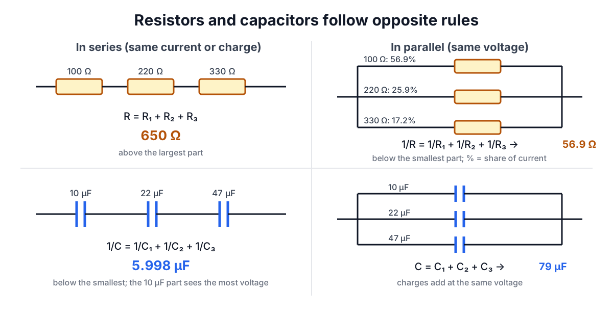
So 100 Ω, 220 Ω and 330 Ω in series make 650 Ω. A series total is always larger than the largest part.
In parallel. The same voltage V is across every resistor and the currents add: I = V/R₁ + V/R₂ + … = V × (1/R₁ + 1/R₂ + …). The combination behaves like one resistor with
1/R = 1/R₁ + 1/R₂ + 1/R₃ + …
The same three resistors in parallel give 1 ÷ (0.01 + 0.004545 + 0.00303) = 56.897 Ω. For exactly two resistors the formula simplifies to the "product over sum", R₁ × R₂ ÷ (R₁ + R₂). Two equal resistors give half the value, and n equal resistors give 1/n.
A parallel total is always smaller than the smallest resistor. The physical reason is that every extra resistor is an extra path; adding a path can only let more current through at the same voltage.
Which resistor gets hot
In a parallel bank the current divides in inverse proportion to resistance. In the example, the 100 Ω resistor carries 56.9% of the total current, the 220 Ω carries 25.9% and the 330 Ω only 17.2%. Power at a common voltage is V² ÷ R, so the smallest resistor also dissipates the most. When paralleling resistors to share power, use equal values; with unequal values, check the rating of the smallest one individually.
In series it is the opposite: the same current flows through all of them, and power I² × R is largest in the largest resistor.
Capacitors: the rules swap
In parallel. Every capacitor has the same voltage V and stores its own charge Q = C × V. The charges add: Q = (C₁ + C₂ + …) × V. So
C = C₁ + C₂ + C₃ + …
10 µF, 22 µF and 47 µF in parallel make 79 µF. This is how bulk capacitance is built up on a power rail, and why designs often put a 100 nF ceramic beside a large electrolytic: the totals add while each part handles a different frequency range.
In series. Charge that leaves one plate must arrive at the next, so every capacitor in a series string carries the same charge Q, while the voltages add: V = Q/C₁ + Q/C₂ + …. That gives
1/C = 1/C₁ + 1/C₂ + 1/C₃ + …
The same three capacitors in series make 5.998 µF, less than the smallest. Two equal capacitors in series make half the value of one.
The rules swap because capacitance is "charge per volt" while resistance is "volts per amp". Elastance, 1/C, follows the resistor rules exactly; it is just rarely used.
Voltage sharing in series capacitors
Because each series capacitor carries the same charge, its voltage is Q ÷ C: the smallest capacitor sees the largest voltage. Two 100 nF parts share a voltage equally, but 100 nF in series with 470 nF puts 82% of the voltage across the 100 nF part.
Engineers stack capacitors in series to reach a higher voltage rating, for example two 400 V electrolytics for an 800 V bus. In DC service the sharing is then set by leakage current, not capacitance, and leakage varies widely between parts. The standard fix is a balancing resistor across each capacitor, chosen to carry several times the maximum leakage current so the resistors, not the leakage, set the voltage split.
Inductors
Inductors follow the resistor rules, because V = L × dI/dt has the same form as V = I × R with dI/dt in place of I. In series, L = L₁ + L₂ + …; in parallel, 1/L = 1/L₁ + 1/L₂ + ….
That is only true when the coils do not share magnetic flux. Two windings on one core, or air coils placed close together, have a mutual inductance M. In series aiding they total L₁ + L₂ + 2M; in series opposing, L₁ + L₂ − 2M. The calculator assumes no coupling, which is a fair assumption for separate shielded inductors spaced apart on a board.
Reducing a mixed network
Real circuits mix both connections. The method is to find the innermost group that is purely series or purely parallel, replace it with its equivalent, and repeat. The calculator's expression mode does exactly this, with + for series and || for parallel. Like × in arithmetic, || is evaluated before + unless brackets say otherwise.
Take (220 + 330) || (470 + 100):
- Inside the first brackets, 220 + 330 = 550 Ω.
- Inside the second, 470 + 100 = 570 Ω.
- 550 Ω in parallel with 570 Ω = 550 × 570 ÷ 1,120 = 279.91 Ω.
The same approach works for capacitors with the swapped rules. (100n || 220n) + 470n: the parallel pair makes 320 nF, then 320 nF in series with 470 nF gives 1 ÷ (1/320 + 1/470) = 190.38 nF.
Networks that cannot be reduced this way, such as a bridge with a resistor across the middle, need delta-to-star conversion or nodal analysis. Writing such a network as a single expression is not possible, which is a useful sign that you have reached the limit of the series/parallel method.
Making values you cannot buy
Combining parts is a practical way to reach an odd value from a limited stock:
- 5 kΩ: two 10 kΩ in parallel, exactly. Or 4.7 kΩ + 300 Ω in series.
- 5.8 kΩ: 4.7 kΩ + (2.2 kΩ || 2.2 kΩ) = 4.7 + 1.1 = 5.8 kΩ.
- Fine-tuning: a large resistor in parallel nudges a value down slightly. 10 kΩ || 1 MΩ = 9.90 kΩ, a 1% trim.
Remember tolerances carry through. A combination of 5% resistors is still only good to roughly 5%, though random errors partly cancel when many parts are combined.
Common mistakes
- Applying the resistor rules to capacitors, or vice versa.
- Forgetting to invert at the end of the reciprocal sum: 1/R₁ + 1/R₂ gives conductance, not resistance.
- Mixing units, such as 4.7k with 220 in a list that assumes kΩ. The calculator reads every value with its own prefix.
- Assuming parallel resistors share power equally when their values differ.
- Stacking capacitors in series for voltage without balancing resistors.
Related reading and tools
- Parallel resistances appear in every loaded divider: see Voltage Divider Design and the Voltage Divider Calculator.
- Capacitor values on the parts themselves are coded; Reading Capacitor Codes and the Capacitor Code Calculator decode them.
- Resistor and capacitor combinations set filter corners in the RC Filter Calculator; the RC filter guide explains the maths.
- For Ohm's law itself and the E-series values, see Ohm's Law, Resistor Color Codes and Voltage Drop Explained.