
RC Filter Cutoff Frequency: Where 1/(2πRC) Comes From
The derivation of fc = 1/(2πRC), what −3 dB and 20 dB per decade mean, the link to the time constant, and the loading and tolerance effects that move real filters.
· 10 min read
fc = 1 ÷ (2πRC) is one of the most used formulas in electronics, and one of the least questioned. Where does the 2π come from? Why is the cutoff defined at −3 dB rather than at the point where the signal is "gone"? Why does a filter that looks right on paper give a different corner on the bench? This post derives the formula from the capacitor's impedance, connects it to the time constant, explains the Bode plot, and works through the loading and tolerance effects that move real filters. Numbers come from the RC Filter Calculator, which solves for fc, R, C or L and draws the Bode plot.
The capacitor as a frequency-dependent resistor
A capacitor passes current in proportion to how fast the voltage across it changes: I = C × dV/dt. For a sine wave V = V₀ sin(2πft), the derivative brings out a factor of 2πf, so the current amplitude is 2πfC × V₀ and it leads the voltage by 90°. Dividing voltage by current gives the capacitor's reactance:
Xc = 1 ÷ (2πfC)
That is where the 2π comes from: frequency f in hertz is cycles per second, while the sine function works in radians, and one cycle is 2π radians. Engineers often write ω = 2πf (angular frequency, in rad/s) to keep the formulas tidy.
At low frequency Xc is huge, so the capacitor looks like an open circuit. At high frequency it is tiny, so it looks like a short. An RC filter uses that changing "resistance" in a voltage divider.
Deriving fc = 1 ÷ (2πRC)
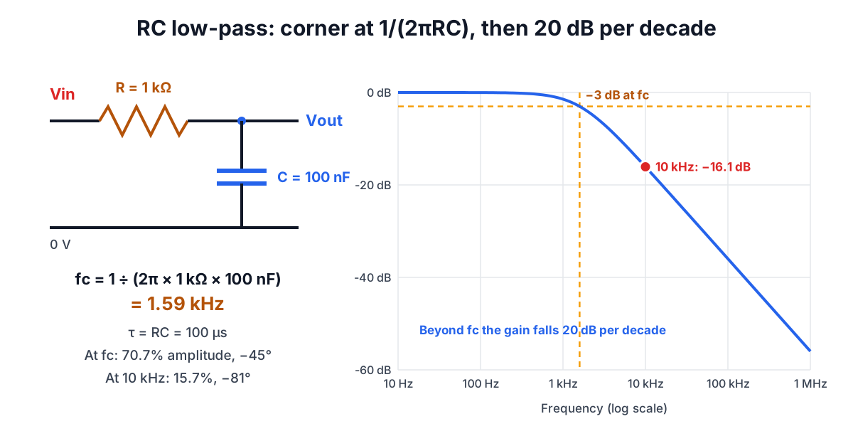
In the low-pass filter the input drives R, and the output is taken across C to ground. It is a divider, but with complex impedances because of the 90° phase shift. Using Zc = 1 ÷ (jωC):
H = Zc ÷ (R + Zc) = 1 ÷ (1 + jωRC)
Its magnitude and phase are
|H| = 1 ÷ √(1 + (ωRC)²), phase = −atan(ωRC)
Define the cutoff as the frequency where ωRC = 1, which is where the resistor and the capacitor's reactance are equal in size. Then
ωc = 1 ÷ RC, so fc = 1 ÷ (2πRC)
At that frequency |H| = 1 ÷ √2 = 0.707 and the phase is −45°. In decibels, 20 × log10(0.707) = −3.01 dB. Power goes as the square of amplitude, so 0.707² = 0.5: the cutoff is the half-power point. That is why it is called the −3 dB frequency, and why it is chosen as the corner: it is where the two asymptotes of the response meet, not where the signal disappears.
For 1 kΩ and 100 nF: fc = 1 ÷ (2π × 1,000 × 100 × 10⁻⁹) = 1,591.5 Hz.
The high-pass version takes the output across R instead: H = jωRC ÷ (1 + jωRC). Same cutoff, same −3 dB, but the phase is +45° at fc and the filter passes high frequencies instead of low ones.
Reading the Bode plot
A Bode magnitude plot uses a logarithmic frequency axis and decibels for gain, which turns the response into nearly straight lines.
- Well below fc (low-pass), (f/fc)² is negligible and |H| ≈ 1, a flat line at 0 dB.
- Well above fc, |H| ≈ fc ÷ f. Every tenfold increase in frequency divides the output by ten, which is −20 dB per decade (equivalently about −6 dB per octave).
- At fc the true curve sits 3 dB below the corner where those two straight lines meet.
Some reference points for a first-order low-pass:
| f / fc | Gain | Amplitude passed | Phase |
|---|---|---|---|
| 0.1 | −0.04 dB | 99.5% | −5.7° |
| 0.5 | −0.97 dB | 89.4% | −26.6° |
| 1 | −3.01 dB | 70.7% | −45° |
| 2 | −6.99 dB | 44.7% | −63.4° |
| 10 | −20.04 dB | 9.95% | −84.3° |
| 100 | −40.00 dB | 1.0% | −89.4° |
The practical lesson: a first-order filter is gentle. At ten times fc it still passes about 10% of the amplitude. If you need a signal at 10 kHz attenuated by 40 dB, a single RC stage needs its corner at about 100 Hz.
In the example filter, 10 kHz is 6.3 times fc, and the calculator gives −16.07 dB (15.7% of the amplitude) with a phase of −81°.
The same circuit in the time domain
Apply a voltage step instead of a sine wave and the capacitor charges exponentially:
Vout(t) = Vin × (1 − e^(−t/τ)), where τ = RC
After one time constant the output reaches 63.2% of the step; after three, 95%; after five, 99.3%. The 10% to 90% rise time is τ × (ln 0.9 − ln 0.1) = 2.197τ. Since τ = 1 ÷ (2πfc), that is rise time ≈ 0.35 ÷ fc, a rule used to relate oscilloscope bandwidth to the fastest edge it can show.
The 1 kΩ / 100 nF filter has τ = 100 µs, settles in about 0.5 ms and has a rise time of 220 µs. The frequency and time views describe the same circuit: a lower cutoff means a slower response.
RL filters
An inductor's reactance rises with frequency, XL = 2πfL, the mirror image of a capacitor. In an RL low-pass the inductor is in series and the output is across the resistor; the cutoff is where R = 2πfL:
fc = R ÷ (2πL), τ = L ÷ R
100 Ω with 10 mH gives the same 1.59 kHz corner as the RC example. At signal level RC filters are usually preferred because capacitors are smaller, cheaper and closer to ideal. Inductors earn their place in power circuits, where they carry large currents with little loss, such as the LC output filter of a switching regulator. Real inductors bring their own complications: winding resistance adds to R, and the core can saturate at high current.
Why real filters miss the calculated corner
The formula assumes a perfect source (zero output impedance) and a perfect load (infinite input impedance). Neither exists.
- Source impedance adds in series with R. A 600 Ω audio source driving a 1 kΩ / 100 nF filter has an effective R of 1.6 kΩ and a corner near 995 Hz, not 1.59 kHz.
- Load resistance sits in parallel with C. A low-pass loaded by RL becomes a divider at DC (passband gain RL ÷ (R + RL)) and its corner rises to 1 ÷ (2π × (R ∥ RL) × C). Keep the load at least ten times R, or buffer the output with an op-amp follower.
- Component tolerance moves fc in proportion. A ±10% capacitor and a ±1% resistor give a corner that can be anywhere within about ±11%.
- Capacitor type matters. Class 2 ceramics such as X7R lose capacitance with DC bias and temperature, shifting fc. Use C0G or film capacitors where the corner must hold (see Reading Capacitor Codes).
- Cascading stages without buffers does not give two independent first-order responses. The second stage loads the first, softening the knee. Either buffer between stages, make the second stage's impedance much higher, or design a proper second-order active filter.
Design judgment: choosing R and C
Since only the product RC sets the corner, there is a free choice of scale. Some guidelines:
- Pick R first, in the 1 kΩ to 100 kΩ range, to suit the source and load: high enough not to load the source, low enough that the next stage does not load the filter.
- Then calculate C. For fc = 1 kHz and R = 10 kΩ, C = 15.9 nF.
- Round C to a stock value (capacitors come in E6 or E12 steps), then recalculate R and round it to E24 or E96. 15 nF with 10.7 kΩ lands within 1% of 1 kHz, where 15 nF with 10 kΩ would land at 1.06 kHz.
- Place the corner with margin. For an anti-aliasing filter ahead of an ADC sampling at 20 kHz, a single RC with fc = 1 kHz gives only about −20 dB at the 10 kHz Nyquist frequency. Higher-order filters or oversampling are the usual answer when more rejection is needed.
For smoothing a 20 kHz PWM signal into DC, the trade-off runs the other way: 10 kΩ and 1 µF give fc = 15.9 Hz, cutting the ripple by about 62 dB, but τ = 10 ms means the output takes around 50 ms to settle after a duty-cycle change.
Related reading and tools
- Build an odd R or C from stock parts with the Series and Parallel Calculator and Series and Parallel Circuits.
- Decode the capacitor you picked with the Capacitor Code Calculator.
- A resistive divider is the DC special case of this circuit; see Voltage Divider Design and the Voltage Divider Calculator.