
LED Current-Limiting Resistors: The Formula and the Judgment
Why an LED needs a resistor, how R = (Vs − n·Vf) / I comes from the diode curve, how much headroom to leave, and how to wire series and parallel strings safely.
· 9 min read
Every LED tutorial says "add a resistor", and most give the formula without explaining why it works or when it stops working. This post goes through the physics behind the current-limiting resistor, the standard formula and where it comes from, the numbers that matter in practice (forward voltage, headroom, wattage) and the wiring mistakes that kill LEDs. Every example can be reproduced in the LED Resistor Calculator. Results are for hobby and preliminary design work; mains-powered or safety-related lighting should follow the relevant product standard and be checked by a qualified person.
Why an LED cannot simply be connected to a supply
A resistor obeys Ohm's law: double the voltage and the current doubles. An LED does not. It is a diode, and its current follows an exponential curve described by the Shockley diode equation, I = Is × (e^(V / (n·Vt)) − 1), where Vt is about 26 mV at room temperature. Below a threshold almost nothing flows. Once the voltage reaches the forward voltage Vf, a small increase in voltage produces a very large increase in current. For a typical indicator LED near 20 mA, an extra 0.1 V across the diode can double the current or more.
That steep curve means the LED cannot set its own current from a fixed voltage. Connect a red LED directly to a 3 V supply and the current is limited only by the battery's internal resistance and the LED's small bulk resistance, which is usually enough to destroy it. Even if a particular supply happens to land at the right voltage, temperature changes everything: Vf falls by roughly 2 mV per °C, so as the LED warms it draws more current, which warms it further.
The fix is to put something in series whose voltage changes in proportion to current. A resistor does exactly that. Most of the "spare" supply voltage sits across the resistor, so when the LED's Vf drifts by a few tenths of a volt the current changes only a little.
Deriving the formula
Kirchhoff's voltage law says the voltages around the loop must add up to the supply. With n LEDs in series, each dropping Vf, and a resistor R carrying current I:
Vs = n × Vf + I × R
Rearranged for the resistor:
R = (Vs − n × Vf) ÷ I
The resistor's power follows from P = I² × R, or equivalently (Vs − n × Vf) × I. Each LED dissipates Vf × I, and the supply delivers Vs × I per string.
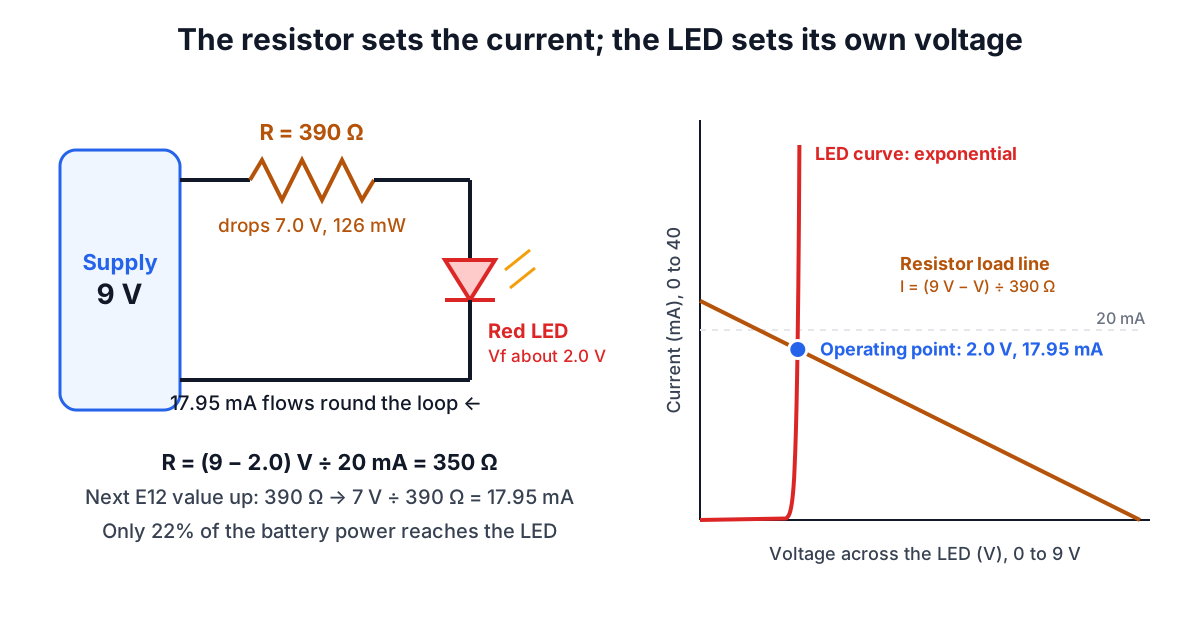
The formula treats Vf as a constant, which is the one real simplification. In the diagram above, the operating point is where the LED's curve meets the resistor's straight "load line". Because the LED curve is so steep near 20 mA, treating Vf as fixed gives an answer within a few percent of a full graphical solution, which is better than the tolerance of the parts anyway.
A worked example
A red LED on a 9 V battery, aiming for 20 mA:
- Voltage left for the resistor: 9 − 2.0 = 7 V.
- Exact resistance: 7 ÷ 0.020 = 350 Ω.
- 350 Ω is not a standard value. In the E12 series the neighbours are 330 Ω and 390 Ω. Rounding up to 390 Ω gives 7 ÷ 390 = 17.95 mA; rounding down to 330 Ω gives 21.2 mA.
- Resistor power at 390 Ω: 0.01795² × 390 = 126 mW.
A common quarter-watt resistor is technically rated above 126 mW, but designers normally keep a resistor at or below half its rating, so the calculator recommends a 1/2 W part. Notice also that only 22% of the battery's power reaches the LED. The other 78% heats the resistor. Two or three LEDs in series on the same 9 V would use the energy far better.
Forward voltage: the number everyone guesses
Forward voltage depends on the semiconductor's band gap, which is why it tracks colour. Typical values at 20 mA from manufacturer datasheets:
| LED type | Typical Vf | Usual range |
|---|---|---|
| Infrared (850 to 940 nm) | 1.3 V | 1.2 to 1.6 V |
| Red | 2.0 V | 1.8 to 2.2 V |
| Yellow, amber | 2.1 V | 1.9 to 2.4 V |
| Yellow-green (GaP) | 2.2 V | 2.0 to 2.4 V |
| Blue, white, true green (InGaN) | 3.2 V | 2.9 to 3.5 V |
| UV (395 to 405 nm) | 3.4 V | 3.1 to 3.8 V |
White LEDs are blue chips with a yellow phosphor, so they share blue's forward voltage. The datasheet's "typical" Vf is measured at a stated test current; at lower currents Vf is a little lower.
The spread in the table matters more than the typical value. Take three white LEDs on a 12 V supply: 3 × 3.2 = 9.6 V, leaving 2.4 V for a 120 Ω resistor and 20 mA. If the LEDs come in at 3.0 V each, the resistor sees 3.0 V and the current becomes 25 mA. If they come in at 3.4 V, it sees 1.8 V and the current falls to 15 mA. A ±0.2 V spread per LED moves the current by ±25%. The calculator shows this spread for your inputs below the result.
Headroom: how much voltage to leave for the resistor
The example above shows the general rule. The fraction by which the current changes is roughly the change in total Vf divided by the voltage across the resistor. With 7 V across the resistor, a 0.2 V shift barely matters (3%). With 0.5 V across it, the same shift is a 40% change.
A sensible target is to leave at least 1 V, or 10 to 20% of the supply, across the resistor. That is why the calculator warns when the resistor voltage falls below 10% of the supply or 0.5 V. Two common cases sit on the wrong side of that line:
- A white LED on 3.3 V. 3.3 − 3.2 = 0.1 V for the resistor. The current depends almost entirely on the individual LED and on temperature. Use a lower-Vf colour, a higher supply, or a constant-current driver.
- Four white LEDs on 12 V. 4 × 3.2 = 12.8 V, more than the supply. They may glow faintly, or not at all. Three per string is the maximum.
Also design for the highest supply voltage the circuit will see. A car's "12 V" is about 12.6 V at rest and 13.8 to 14.4 V with the engine running. A resistor chosen for 12.0 V lets noticeably more current through at 14.4 V.
Series strings, parallel strings and the shared-resistor trap
LEDs in series all carry the same current, so one resistor per string is correct and efficient: more of the supply voltage goes into light and less into heat. The limit is that the total Vf must stay comfortably below the supply.
When you need more LEDs than one string can hold, add parallel strings, each with its own resistor. Do not connect several LEDs or strings in parallel and feed them through one shared resistor. Their forward voltages are never identical, and because the diode curve is so steep, the LED with the lowest Vf takes a disproportionate share of the current. It runs hotter, its Vf falls further, and it takes even more. One shared resistor sized for "4 × 20 mA" can easily put 40 mA through one LED and 10 mA through another.
For four strings of three white LEDs on 12 V the calculator gives 120 Ω per string, 48 mW per resistor, and 80 mA and 0.96 W from the supply. Each resistor needs only a small rating; the power supply needs to provide the total.
Choosing the resistor's wattage
Resistors are specified at a maximum power at an ambient temperature, commonly 70 °C, and derate linearly above it. Running at the full rating means a hot part, and a hot part drifts and ages faster. The usual practice is to choose a rating at least twice the calculated dissipation, which is what the calculator recommends: 60 mW becomes a 1/8 W part, 126 mW becomes 1/2 W.
On surface-mount boards the package sets the rating: roughly 1/16 W for 0402, 1/10 W for 0603, 1/8 W for 0805 and 1/4 W for 1206 in typical thick-film ranges, but check the specific series' datasheet.
When a resistor is the wrong answer
A resistor is ideal for indicator LEDs at 1 to 30 mA. It becomes a poor choice when:
- The current is large. A 1 W white power LED at 350 mA from 5 V would put 0.63 W into the resistor. A constant-current buck driver wastes far less.
- The supply varies a lot. A Li-ion cell runs from 4.2 V down to about 3.0 V. With a white LED, the resistor's share swings from 1 V to almost nothing, and so does the brightness.
- Brightness must be precise. Constant-current drivers, or a transistor current source, hold the current regardless of Vf and supply.
- You need dimming. PWM through a MOSFET with a resistor still in series works well; varying the resistor value does not dim evenly because perceived brightness is not linear in current.
Common mistakes
- Using the full supply voltage in Ohm's law instead of the voltage left after the LEDs.
- Forgetting the LED needs the right polarity. A reversed LED blocks current, but most LEDs only tolerate about 5 V in reverse, so a reversed LED on a higher AC or DC voltage can be damaged.
- Guessing Vf from colour on a high-power or unusual part. Measure it or read the datasheet.
- Ignoring the GPIO pin's current limit when driving an LED from a microcontroller. Keep to 5 to 10 mA, or use a transistor.
Related reading and tools
- The resistor only works because Ohm's law holds for it: see Ohm's Law, Resistor Color Codes and Voltage Drop Explained and the Ohm's Law Calculator.
- To identify the resistor you picked, use the Resistor Color Code Calculator.
- If your LED is fed from a divided-down voltage, read Voltage Divider Design first; a divider is not a good LED supply.
- Combining resistors to reach an odd value is covered in Series and Parallel Circuits, with the Series and Parallel Calculator.