
Voltage Divider Design: Ratios, Loading and Picking Real Resistors
Derive Vout = Vin·R2/(R1+R2), see why a load pulls the output down, use the Thevenin view to size values, and choose standard resistor pairs for ADC inputs.
· 9 min read
Two resistors and a wire in between: the voltage divider is the first circuit most people meet after Ohm's law, and also one of the most quietly misused. The formula is easy. Making a divider that gives the right voltage once something is connected to it takes a little more thought. This post derives the formula, shows how a load changes it, introduces the Thevenin view that makes sizing obvious, and walks through choosing real standard resistors for a battery monitor. You can follow along in the Voltage Divider Calculator. It is written for preliminary design; high-voltage dividers in particular need resistors rated for the voltage and a review against the applicable safety standard.
Deriving Vout = Vin × R2 ÷ (R1 + R2)
Put R1 and R2 in series across a source Vin, with R1 at the top and R2 to ground. With nothing else connected, the same current flows through both:
I = Vin ÷ (R1 + R2)
The output is the voltage across R2, which by Ohm's law is I × R2:
Vout = Vin × R2 ÷ (R1 + R2)
The fraction R2 ÷ (R1 + R2) is the divider ratio. It is always between 0 and 1, so a resistive divider can only make a voltage smaller, never larger. Rearranging gives the two design forms:
- R2 = R1 × Vout ÷ (Vin − Vout)
- R1 = R2 × (Vin − Vout) ÷ Vout
Notice that only the ratio of the resistors sets Vout. 1 kΩ over 2 kΩ, 10 kΩ over 20 kΩ and 1 MΩ over 2 MΩ all give two thirds of the input on paper. The absolute values decide everything else: the current wasted, the power in each resistor, how much a load disturbs the output and how much noise it picks up.
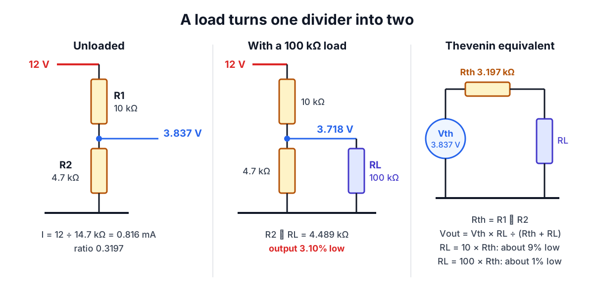
A quick check with the calculator: 12 V across 10 kΩ and 4.7 kΩ gives a ratio of 4.7 ÷ 14.7 = 0.3197, so Vout = 3.8367 V. The divider draws 0.816 mA and the two resistors dissipate 6.7 mW and 3.1 mW.
What a load does to the output
Real dividers feed something: an ADC pin, an op-amp input, a transistor base, a meter. That load has a resistance RL, and it sits in parallel with R2. The effective bottom resistance becomes
R2' = R2 × RL ÷ (R2 + RL)
which is always less than R2, so the output always drops. Add a 100 kΩ load to the 12 V divider above: R2' = 4.489 kΩ and Vout falls to 3.7179 V, 3.1% below the unloaded value. A 3% error is nothing for an LED threshold and a lot for a battery state-of-charge reading.
The Thevenin view: a divider is a source with a resistor
Thevenin's theorem says any linear network of sources and resistors, seen from two terminals, behaves like a single voltage source in series with a single resistance. For a divider:
- Thevenin voltage: the unloaded output, Vth = Vin × R2 ÷ (R1 + R2).
- Thevenin resistance: R1 and R2 in parallel, Rth = R1 × R2 ÷ (R1 + R2), because the ideal source Vin looks like a short circuit when you look back into the network.
For the 10 kΩ / 4.7 kΩ divider, Rth = 3.197 kΩ. Now a load RL simply forms a second divider with Rth:
Vout = Vth × RL ÷ (Rth + RL)
This gives the rule of thumb that makes divider design quick. If RL is 10 times Rth, the output is about 9% low. If RL is 100 times Rth, it is about 1% low. For 0.1%, you need RL around 1,000 times Rth. So decide how much loading error you can tolerate, look up the input resistance of whatever the divider feeds, and size Rth accordingly. Then choose R1 and R2 to give that Rth and the right ratio.
How big should the resistors be?
The Thevenin view pushes resistances down; power and battery life push them up. Some typical considerations:
- Current drain. A divider draws Vin ÷ (R1 + R2) all the time. A 1 kΩ + 1 kΩ divider on 12 V draws 6 mA; over a month that is 4.3 Ah, enough to flatten a small battery. 100 kΩ + 100 kΩ draws 60 µA.
- ADC inputs. A microcontroller's successive-approximation ADC charges a small sampling capacitor through the source resistance. Many datasheets ask for a source impedance of 10 kΩ or less (check yours). A larger Rth gives low or noisy readings unless you add a capacitor of 10 to 100 nF from the output to ground, which supplies the sampling charge.
- Leakage and bias currents. Op-amp inputs draw a bias current. With megohm resistors, nanoamps of bias current produce millivolts of error.
- Noise. Higher resistances have more thermal noise and pick up more interference from nearby signals.
- Power and voltage rating. On a 400 V DC bus even a 1 MΩ top resistor dissipates 0.16 W, and ordinary 1/4 W resistors are typically rated for a maximum working voltage of 200 to 250 V. Split a high-voltage R1 into several resistors in series.
For most low-voltage signal work, total resistances between about 10 kΩ and 100 kΩ are a reasonable starting range.
Picking standard resistors: a battery monitor example
Suppose you want to read a 24 V battery bank with a 3.3 V ADC. The ratio is 3.3 ÷ 24 = 0.1375. With R1 = 10 kΩ the exact R2 is 10 × 3.3 ÷ 20.7 = 1.594 kΩ, which is not a value you can buy.
Searching E24 pairs gives several close fits. The calculator ranks them:
- 4.7 kΩ over 750 Ω: 3.3028 V (+0.08%), but it draws 4.4 mA.
- 27 kΩ over 4.3 kΩ: 3.2971 V (−0.09%), drawing 0.77 mA with an Rth of 3.7 kΩ.
The second pair is just as accurate, uses a sixth of the current and still has an Rth below 10 kΩ, so it is the better choice. Two more judgment calls finish the design:
- Leave headroom. A "24 V" lead-acid bank reaches about 28.8 V while charging. At that voltage the 27 k / 4.3 k divider outputs 3.96 V, above the ADC's range. Design for the maximum input instead: 3.3 ÷ 30 gives a ratio of 0.11, and then scale readings in software.
- Account for tolerance. With two 1% resistors at opposite extremes the ratio can move by nearly 2%. The calculator's worst-case figure shows the range. If that matters, use 0.1% resistors or calibrate each unit once.
When not to use a divider
The commonest misuse is trying to power something from a divider: dropping 12 V to 5 V for a USB device, or to 3.3 V for a sensor module. The load draws current, which by the Thevenin view drops the voltage, and the current varies with what the device is doing, so the voltage varies too. Meanwhile most of the power is lost in the resistors. Use a linear regulator or a buck converter.
Dividers are also a poor choice for fast or bidirectional logic signals. The resistances and the input capacitance of the receiving pin form an RC low-pass filter (see the RC filter guide), rounding the edges. For I²C, SPI at speed or anything bidirectional, use a level-shifter chip.
Common mistakes
- Taking the output across R1 instead of R2, which gives Vin minus the expected value.
- Forgetting that the meter used to check the circuit is itself a load. A 10 MΩ meter on a divider made of 1 MΩ resistors reads several percent low.
- Ignoring the worst-case supply voltage, so the output exceeds an ADC's absolute maximum.
- Choosing very low values "for accuracy" and draining a battery in standby.
Related reading and tools
- The Series and Parallel Calculator handles the R2 ∥ RL step, and Series and Parallel Circuits explains it.
- The LED Resistor Calculator covers the other everyday resistor job; LED Current-Limiting Resistors explains why a divider makes a poor LED supply.
- For the background on Ohm's law and E-series values, see Ohm's Law, Resistor Color Codes and Voltage Drop Explained.