
Op-Amp Gain Formulas: Inverting, Non-Inverting and Beyond
Derive the inverting, non-inverting, difference and summing gain formulas from two golden rules, then see where real op-amps fall short: rails, GBW, noise gain and resistor matching.
· 11 min read
Every op-amp textbook gives the same two gain formulas, −Rf ÷ Rin and 1 + Rf ÷ Rg, and every lab bench eventually shows a circuit that does not follow them: the output flattens at 13 V, the gain falls off at a few kilohertz, or a difference amplifier lets through hum it was meant to reject. This post derives the gain formulas for the five common circuits from two simple rules, then works through the limits that real parts impose. The numbers come from the Op-Amp Gain Calculator, which checks gain, output swing, bandwidth and resistor choices together.
The two golden rules
An ideal op-amp has infinite open-loop gain, infinite input impedance and zero output impedance. With negative feedback connected, two working rules follow:
- No current flows into either input.
- The output does whatever it must to make the two input voltages equal.
Rule 2 is the consequence of huge gain: if the inputs differed by even a microvolt, an open-loop gain of a million would drive the output a volt away, and the feedback would pull the inputs back together. Every gain formula below drops out of these two rules and Ohm's law.
Inverting amplifier
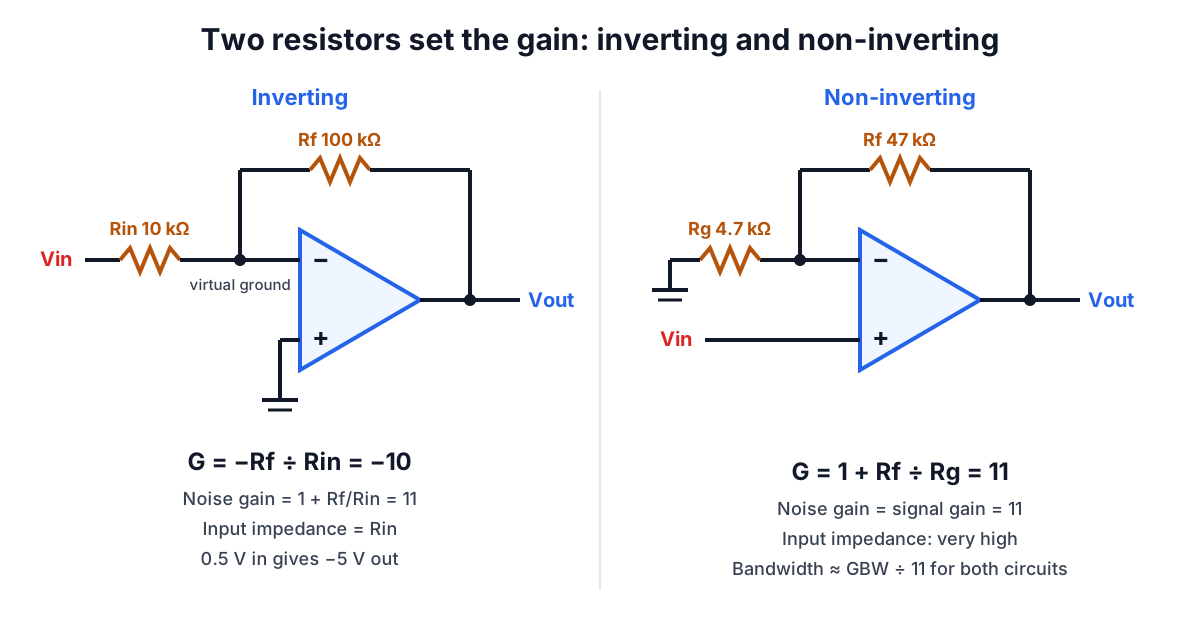
The non-inverting input is grounded, so by rule 2 the inverting input also sits at 0 V. It is called a virtual ground: it stays at ground potential without being connected to it. The current through Rin is Vin ÷ Rin. By rule 1 none of it enters the op-amp, so it all flows through Rf, and the output must sit at −(Vin ÷ Rin) × Rf. Therefore:
G = Vout ÷ Vin = −Rf ÷ Rin
With Rf = 100 kΩ and Rin = 10 kΩ, G = −10 (20 dB), and 0.5 V in gives −5 V out. The input impedance is just Rin, because the source sees Rin going to a virtual ground. That is the inverting stage's main drawback: a high gain with a high input impedance needs an enormous Rf.
Non-inverting amplifier and follower
Now the signal goes to the non-inverting input, and Rf and Rg form a divider from the output to ground with the inverting input at its centre. That input sees Vout × Rg ÷ (Rf + Rg), and by rule 2 this must equal Vin:
G = 1 + Rf ÷ Rg
With Rf = 47 kΩ and Rg = 4.7 kΩ, G = 11 (20.83 dB). The input impedance is the op-amp's own input impedance, typically megohms to teraohms, so this is the circuit to use when the source cannot supply current. The gain can never be less than 1.
Set Rf = 0 (a wire) and remove Rg, and G = 1: the voltage follower. It does not amplify, but it copies a high-impedance voltage onto a low-impedance output, which is how a voltage divider is buffered so its load does not pull it down.
Difference and summing amplifiers
The four-resistor difference amplifier combines both: V1 drives the inverting side through R1 with R2 as feedback, and V2 drives the non-inverting input through a divider R3 and R4. Superposition gives:
Vout = V2 × R4 ÷ (R3 + R4) × (1 + R2 ÷ R1) − V1 × R2 ÷ R1
When R4 ÷ R3 = R2 ÷ R1 this collapses to Vout = (R2 ÷ R1) × (V2 − V1). With 10 kΩ and 100 kΩ in both positions, 1.1 V and 1.0 V produce exactly 1.0 V.
The summing amplifier is an inverting stage with several input resistors meeting at the virtual ground. Because that node stays at 0 V, each input contributes its own current without disturbing the others:
Vout = −Rf × (V1 ÷ R1 + V2 ÷ R2 + …)
With Rf = 100 kΩ, 1 V through 10 kΩ and 0.5 V through 20 kΩ, the output is −(10 + 2.5) = −12.5 V. Audio mixers are built this way.
Limit 1: the output cannot reach the rails
An op-amp's output stage needs some voltage across its transistors. Classic bipolar parts such as the 741 or the JFET-input TL07x swing to within about 1.5 to 2 V of each rail at moderate load, so on ±15 V the output tops out near ±13.5 V. Rail-to-rail output parts get within tens of millivolts at light load, but not under heavy load. When the ideal output would exceed the swing limit, the op-amp saturates and the waveform clips flat.
With an inverting gain of −23 and 1 V in, the ideal output is −23 V, but on ±15 V with 1.5 V of swing loss the real output stops at −13.5 V. The calculator flags this and shows both figures. Input range matters too: a non-inverting stage near the negative rail needs an op-amp whose common-mode input range includes that rail.
Limit 2: gain-bandwidth product and noise gain
Open-loop gain is not infinite. In most voltage-feedback op-amps it falls at 20 dB per decade above a few hertz, so gain times frequency is roughly constant: the gain-bandwidth product (GBW). A closed-loop amplifier keeps its designed gain until the open-loop gain falls to meet it. The −3 dB bandwidth is approximately:
Bandwidth ≈ GBW ÷ noise gain
The noise gain is 1 + Rf ÷ Rin for both inverting and non-inverting stages, because in both the feedback network returns the same fraction of the output to the inverting input. This catches people out. An inverting stage with G = −10 has a noise gain of 11, so a 1 MHz op-amp gives about 90.9 kHz, not 100 kHz. An inverting buffer with G = −1 has a noise gain of 2 and half the bandwidth of a follower. The summing amplifier's noise gain is 1 + Rf ÷ (R1 ∥ R2 ∥ …), which grows with every input added: the example above has a noise gain of 16 and, with 1 MHz GBW, a bandwidth of about 62.5 kHz.
Large signals hit a second limit, slew rate. A 741 slews at about 0.5 V/µs, so a 10 V peak sine wave distorts above roughly 0.5 ÷ (2π × 10) MHz ≈ 8 kHz, regardless of GBW.
Limit 3: resistor matching in the difference amplifier
The difference amplifier's rejection of common-mode voltage depends entirely on R4/R3 matching R2/R1. Any mismatch leaves a common-mode gain:
Acm = R4 ÷ (R3 + R4) × (1 + R2 ÷ R1) − R2 ÷ R1
For a unity-gain stage with every resistor 10 kΩ except R4 at 10.1 kΩ (1% high), Acm ≈ 0.005 and the common-mode rejection ratio falls to about 46 dB. With four random 1% resistors the worst case is worse still. That is why precision difference amplifiers use 0.1% or laser-trimmed networks, and why instrumentation amplifiers exist.
Choosing resistor values
Only the ratio sets the gain, so there is a free choice of scale:
- Too low (below about 1 kΩ) and the feedback network loads the output, wasting current and increasing distortion; in an inverting stage it also loads the source.
- Too high (above a few hundred kilohms) and input bias current times the resistance becomes a noticeable offset, thermal noise rises, and stray capacitance across Rf forms an unintended low-pass filter.
- Around 10 kΩ is a sound default for general-purpose op-amps.
Standard values rarely give a round ratio directly. A gain of −23 with 10 kΩ input needs 230 kΩ feedback, which is not an E24 value, but searching pairs finds 2.7 kΩ and 62 kΩ at −22.963 (−0.161%). A gain of 22 has an exact E24 pair, 1.5 kΩ and 33 kΩ. The calculator's design table does this search and loads a chosen pair with one click.
Related tools and reading
- Gains in dB add along a signal chain; convert with the Decibel Calculator and read Decibels Explained.
- An RC network around an op-amp makes an active filter; the corner frequency follows the same rule as in RC Filter Cutoff Frequency.
- Decode the feedback resistor you pulled from the drawer with the Resistor Color Code Calculator.