
Reactance, Impedance and RLC Resonance: The Phasor View
Why XL rises and XC falls with frequency, how j turns series and parallel RLC into simple algebra, and what resonance, Q and bandwidth mean for real inductors and capacitors.
· 11 min read
Ohm's law works for AC circuits too, as long as "resistance" is allowed to depend on frequency and to shift the phase of the current. That generalised resistance is impedance, and the part contributed by inductors and capacitors is reactance. This post explains where XL = 2πfL and XC = 1 ÷ (2πfC) come from, how complex numbers turn series and parallel RLC circuits into ordinary algebra, and what resonance, Q and bandwidth tell you about a real circuit. The worked numbers come from the Reactance and Impedance Calculator, which does the complex arithmetic and plots |Z| against frequency.
Where reactance comes from
An inductor resists changes in current: V = L × dI/dt. A capacitor resists changes in voltage: I = C × dV/dt. Feed either one a sine wave at frequency f and the derivative pulls out a factor of 2πf, the angular frequency ω, along with a quarter-cycle shift.
For the inductor, a current I₀ sin(ωt) produces a voltage ωL × I₀ cos(ωt). The ratio of amplitudes is XL = ωL = 2πfL, and the voltage leads the current by 90°.
For the capacitor, a voltage V₀ sin(ωt) drives a current ωC × V₀ cos(ωt). The ratio of voltage to current is XC = 1 ÷ (ωC) = 1 ÷ (2πfC), and the current leads the voltage by 90°.
So an inductor's opposition grows with frequency and a capacitor's shrinks. A 100 mH inductor at 60 Hz has XL = 37.70 Ω; a 10 µF capacitor at 60 Hz has XC = 265.3 Ω. At DC the inductor is a short and the capacitor is open; at very high frequency the roles swap.
Complex impedance: why j makes it easy
Adding a resistor's 100 Ω to an inductor's 62.8 Ω does not give 162.8 Ω, because the two voltages are 90° apart and peak at different times. Engineers handle that by writing impedance as a complex number, with j (the square root of −1, since i is taken for current) marking the 90° shift:
- Resistor: Z = R
- Inductor: Z = +jXL
- Capacitor: Z = −jXC
With that notation the ordinary rules for resistors apply unchanged. In series, impedances add: Z = R + j(XL − XC). In parallel, admittances (Y = 1/Z) add: Y = 1/R + j(1/XC − 1/XL), then Z = 1/Y. The magnitude |Z| = √(Re² + Im²) is the ratio of voltage amplitude to current amplitude, and the angle θ = atan(Im ÷ Re) is the phase by which the current lags the voltage. Positive θ means net inductive, negative means net capacitive, and cos θ is the power factor, the fraction of the volt-amperes that does real work. The same idea sits behind power factor correction in AC power systems.
Worked example: a series RLC at 1 kHz
Take R = 100 Ω, L = 10 mH and C = 1 µF at 1 kHz:
- XL = 2π × 1000 × 0.01 = 62.83 Ω
- XC = 1 ÷ (2π × 1000 × 10⁻⁶) = 159.15 Ω
- Z = 100 + j(62.83 − 159.15) = 100 − j96.32 Ω
- |Z| = √(100² + 96.32²) = 138.85 Ω, θ = atan(−96.32 ÷ 100) = −43.93°
The capacitor dominates at this frequency, so the circuit is capacitive and the current leads the voltage by about 44°. The power factor is cos(−43.93°) = 0.720.
Put the same L and C in parallel with 1 kΩ and the picture flips. The inductor now has the lower reactance and takes most of the current, so the combination looks inductive: |Z| = 103.26 Ω at +84.07°. With 10 V applied the current is 96.84 mA, but only the resistor dissipates power, 10² ÷ 1000 = 100 mW.
Resonance
At one frequency the inductive and capacitive reactances are equal. Setting 2πfL = 1 ÷ (2πfC) and solving gives the resonant frequency:
f0 = 1 ÷ (2π√(LC))
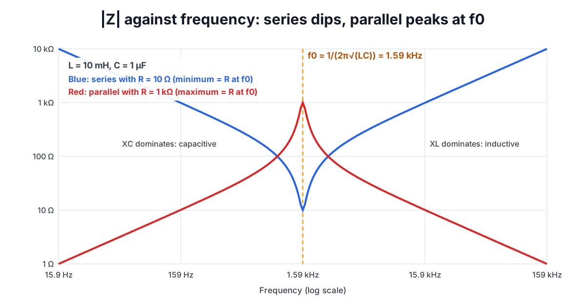
For 10 mH and 1 µF, f0 = 1.5915 kHz. At that frequency both reactances equal √(L/C) = 100 Ω, a quantity called the characteristic impedance.
What happens at f0 depends on the connection:
- Series: the reactances cancel, leaving Z = R. Impedance is at its minimum and current at its maximum, in phase with the voltage. The voltage across L and across C individually can be far larger than the supply, Q times larger, because they are equal and opposite.
- Parallel: the branch currents through L and C are equal and opposite, so they circulate between the two parts and the source supplies only what the resistor takes. Impedance is at its maximum, R; with ideal parts and no resistor it would be infinite. This "tank" circuit is the basis of LC oscillators and IF filters.
Q factor and bandwidth
Q measures how sharp the resonance is, and equivalently how much energy is stored compared with what is lost each cycle. For the two common forms:
- Series RLC: Q = (1/R) × √(L/C). Lower series resistance means higher Q.
- Parallel RLC: Q = R × √(C/L). Higher parallel resistance means higher Q.
The bandwidth between the two half-power (−3 dB) frequencies is BW = f0 ÷ Q. With R = 10 Ω in series, L = 100 µH and C = 100 nF: f0 = 50.33 kHz, √(L/C) = 31.62 Ω, Q = 3.162 and BW = 15.92 kHz.
A subtle point: the band edges are not f0 ± BW/2. They are placed symmetrically on a logarithmic scale, so that f_low × f_high = f0². For the example above they are 43.00 kHz and 58.91 kHz, which differ by exactly 15.92 kHz but sit 7.3 kHz below and 8.6 kHz above f0. The calculator reports the exact edges. For high Q the asymmetry disappears and f0 ± BW/2 is good enough.
When the ideal model breaks down
Real components are not pure reactances, and the differences decide whether a circuit behaves as calculated:
- Inductor resistance. The wire in a coil has resistance, which in a series circuit adds directly to R and limits Q. A 10 mH ferrite inductor might have 5 to 30 Ω of DC resistance, plus extra AC loss in the core at higher frequency.
- Self-resonance. Every inductor has capacitance between its turns and every capacitor has lead and plate inductance. An inductor stops behaving like an inductor above its self-resonant frequency; a 100 nF decoupling capacitor becomes inductive somewhere in the tens of megahertz, depending on package. Datasheets give impedance curves for exactly this reason.
- ESR. A capacitor's equivalent series resistance sets the floor of its impedance curve and heats it under ripple current.
- Tolerance. f0 depends on the square root of LC, so a 10% error in C moves f0 by about 5%. Trimmers or tuned cores are used where the frequency must be exact.
- Non-sinusoidal signals. Reactance is defined for a single frequency. A square wave contains odd harmonics, and each harmonic sees a different impedance. Analyse them one at a time, or simulate.
Using the numbers in design
Reactance shows up everywhere once you look for it. A first-order RC filter's corner is simply the frequency where XC = R; see RC Filter Cutoff Frequency and the RC Filter Calculator. A decoupling capacitor works because its reactance at the noise frequency is far below the impedance of the supply trace. A loudspeaker crossover uses a series inductor whose reactance equals the speaker impedance at the crossover frequency. Combining reactive parts into odd values is covered in Series and Parallel Circuits, and once you have a gain or attenuation figure the Decibel Calculator turns it into dB.