
Power Factor Correction in NSW: kVAr, Ripple Control
Sizing a capacitor bank for a 400 V, 50 Hz installation to the NSW 0.90 lagging minimum, checking it against Table 6-1, and blocking ripple control signals.
By Redbison Dev · · 10 min read
Australia edition. Written for Australian installations under the Service and Installation Rules of NSW (April 2026): the 0.90 lagging to unity requirement, the Table 6-1 multipliers, distributor approval, ripple control blocking and detuning reactors, at 400 V and 50 Hz. Other states set their own rules. US edition
A workshop drawing 120 kW at a power factor of 0.75 is below the NSW minimum. The Service and Installation Rules of NSW require the maximum demand power factor of an installation to sit between 0.90 lagging and unity, and reaching 0.90 takes 47.71 kVAr of capacitors; going on to 0.95 takes 66.39 kVAr. In NSW the bank also has to be approved by the distributor and must not swallow the ripple control signals that switch off-peak hot water. This edition works through all three with the Australian power factor correction calculator, quoting the April 2026 edition of the NSW rules. Other states and distributors publish their own service and installation rules, so check yours before using the NSW figures.
What the NSW rules require
Clause 6.1.1 is short and strict. The customer must keep the maximum demand power factor between 0.90 lagging and unity. If a poor power factor means the network is not used efficiently or another customer's supply is affected, the distributor may require the installation to be metered at an appropriate tariff. And correction equipment, or any change in inductive load, must not:
- make the installation's power factor leading at any time; or
- upset the distributor's frequency injection (ripple) load control system.
Clause 6.3 adds that new load in an existing installation must meet the same minimum, and the distributor may require the whole installation to comply. For multi-tenanted buildings below 0.9, the rules suggest correcting in the house services section, or with the distributor's agreement at the unmetered main switchboard, rather than paying for a supply upgrade.
Sizing the bank
Real power does not change when capacitors are added; only the reactive power does:
kVAr = kW × (tan φ1 − tan φ2), φ = arccos PF
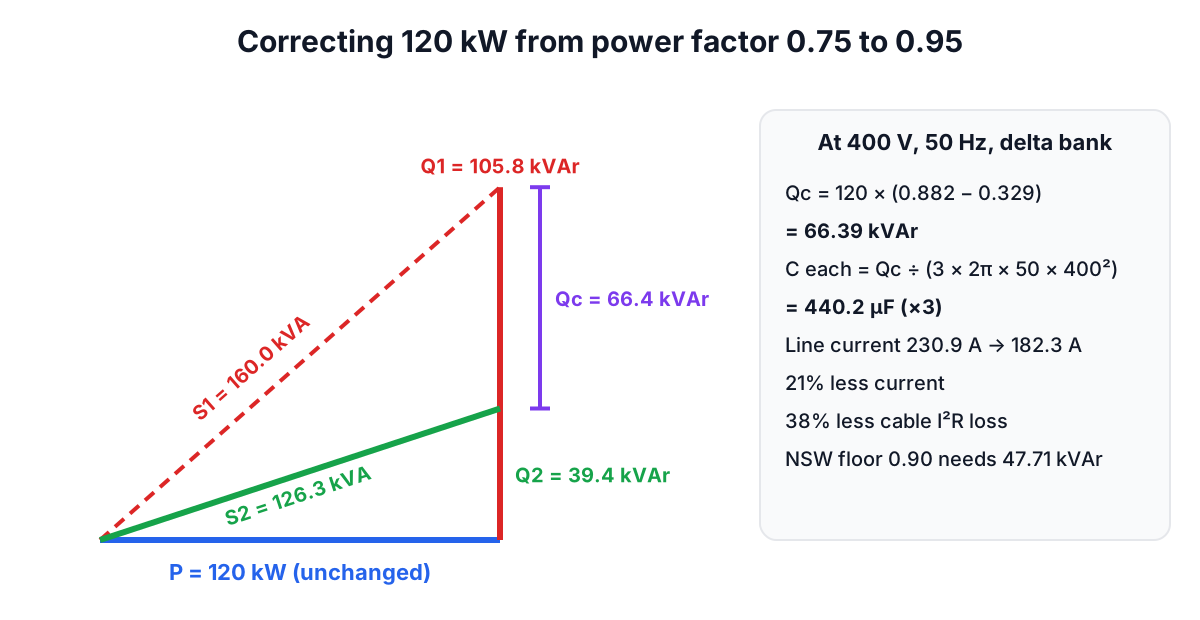
For 120 kW at 0.75, tan φ1 = 0.882. To 0.90 (tan φ2 = 0.484) the bank is 47.71 kVAr; to 0.95 (0.329) it is 66.39 kVAr.
| Target | Bank | Line current at 400 V | kVA at maximum demand |
|---|---|---|---|
| None (0.75) | 0 | 230.9 A | 160.0 |
| 0.90, the NSW floor | 47.71 kVAr | 192.5 A | 133.3 |
| 0.95 | 66.39 kVAr | 182.3 A | 126.3 |
The extra 18.7 kVAr for 0.95 frees another 7 kVA and 10 A. Whether that pays depends on how your network tariff charges for demand.
Checking against Table 6-1
The rules print the bracketed multiplier, tan φ1 − tan φ2, in Table 6-1 for original power factors from 0.50 to 0.98 and targets from 0.80 to unity, in steps of 0.02, as a guide for designers. A few checks against the calculator:
| From | To | Table 6-1 | Calculator | kW | kVAr |
|---|---|---|---|---|---|
| 0.86 | 0.98 | 0.390 | 0.390 | 80 | 31.22 |
| 0.78 | 0.96 | 0.510 | 0.511 | 100 | 51.06 |
| 0.70 | 0.96 | 0.728 | 0.729 | 40 | 29.14 |
The third-decimal differences are rounding in the table. Multiply your kW by the table value for a quick sense check of any quote.
Capacitance at 50 Hz
Low-voltage banks are commonly delta-connected, with each capacitor across 400 V:
C (each) = kVAr × 1,000 ÷ (3 × 2π × 50 × 400²)
The 66.39 kVAr bank is 440.2 µF per capacitor, and the 31.22 kVAr bank in the table is 207.1 µF. In star each unit sees 230 V and must be three times larger. The rules require shunt capacitors to comply with IEC 60831-1:2014 for self-healing units up to 1,000 V.
Approval before you buy
Clause 6.2 requires an application to the distributor for each connection of power factor correction equipment, except where it is fitted to individual items of equipment with low power requirements, and tells you to obtain agreement before committing funds or installing. Because the design is described as complex, the rules recommend using a competent energy management consultant, discussing the design with the distributor before it is manufactured, and submitting impedance improvement equipment for approval before connection.
Automatic banks must switch in steps small enough not to affect the ripple frequency. Larger steps may be accepted where capacitors switch with the equipment as one unit, or in special cases with infrequent switching on a low-impedance supply.
Ripple control: why capacitors need blocking
Distributors inject audio-frequency ripple signals to switch water heaters, street lighting and meter equipment. The rules note that at those frequencies a capacitor's impedance is some 10 to 21 times lower than at 50 Hz, so an unblocked bank soaks up the signal, and in the worst case resonates with the distribution transformer and forms a virtual short circuit on the ripple system. Where the distributor uses ripple control, the customer must install equipment to block it.
Table 6-2 of the rules lists the signal frequencies by area, as at 1 June 2005:
| Distributor | Area | Signal frequency |
|---|---|---|
| Ausgrid | Upper Hunter | 492 and 750 Hz |
| Ausgrid | Hunter Valley | 1050 and 750 Hz |
| Ausgrid | Hunter, other areas | 1050 Hz |
| Ausgrid | Central Coast | 1050 Hz |
| Ausgrid | Manly, Warringah and Mackellar | 1050 Hz |
| Ausgrid | St George | 492 Hz |
| Ausgrid | Sydney, other areas | 750 Hz |
| Endeavour Energy | Thirroul to Kiama | 750 Hz |
| Endeavour Energy | Kandos area | 396 Hz |
| Endeavour Energy | Nowra | 283 Hz |
| Endeavour Energy | Western Sydney | 1050 Hz |
| Essential Energy | Contact the distributor |
A note to the table says Ausgrid's actual frequencies differ slightly from the nominal ones: 492 Hz for 495 Hz, 744 Hz for 750 Hz and 1042 Hz for 1050 Hz. The blocker must work at your area's frequency.
The rules prefer detuning reactors, which tune the bank's resonance below any likely harmonic, over other blocking methods. They also warn that the customer pays for re-inspection if impedance levels are not met, that banks without detuning reactors need protection against switching spikes, and that correction without detuning reactors greatly increases the risk of harmonic damage. A 7% reactor at 50 Hz puts the resonance at about 189 Hz, below the 5th harmonic at 250 Hz.
Never leading
The ban on a leading power factor "at any time" rules out a fixed bank sized for full load on any site whose load falls at night or at weekends. An automatic controller that switches steps out as motors stop, with a target of 0.95 to 0.98 rather than unity, keeps the installation inside the 0.90 to 1.00 band in both directions.
Is it worth it?
The NSW rules say the cost of correction can usually be recovered through lower electricity costs. Any saving comes from network tariffs that charge for demand in kVA or for a poor power factor, not from the kWh the machines use, which stays the same; check how your tariff bills demand. In the example, maximum demand falls from 160.0 kVA to 126.3 kVA, current by 21% and cable losses by about 38%.
Frequently asked questions
What is the minimum power factor in NSW?
Clause 6.1.1 of the Service and Installation Rules of NSW requires the maximum demand power factor of an installation to be between 0.90 lagging and unity. Correction must never make it leading.
Do I need the distributor's approval for a capacitor bank?
Yes. An application is needed for each connection of power factor correction equipment, except small units fitted to individual items of equipment, and agreement should come before you commit funds.
Why does my capacitor bank need a ripple blocker?
Capacitors have a low impedance at ripple control frequencies and absorb the signals distributors use to switch off-peak loads. The NSW rules require blocking equipment where ripple control is used, preferably detuning reactors.
How many kVAr do I need to reach 0.90?
Multiply your kW at maximum demand by tan φ1 − tan φ2, or by the Table 6-1 value. From 0.75 to 0.90 the calculator's multiplier is 0.398, between the table's 0.425 (from 0.74) and 0.371 (from 0.76), so 120 kW needs 47.71 kVAr.
Sources and further reading
- Service and Installation Rules of NSW (April 2026), Section 6, NSW Department of Climate Change, Energy, the Environment and Water. Clauses 6.1 to 6.4, Table 6-1 multipliers and Table 6-2 ripple frequencies.
- IEC 60831-1:2014 Shunt power capacitors of the self-healing type, International Electrotechnical Commission. The capacitor standard the NSW rules cite.
- Reducing power factor cost, US Department of Energy. Why low power factor costs money and how capacitors help.
- kVAh billing implementation, MSEDCL. How a low power factor raises current and the transformer size needed for the same kW.
- General Specifications for Electrical Works, Part I (2013), Central Public Works Department, India. Current and loss reductions from correction and the effects of a leading power factor.
Open the Power Factor Correction Calculator
More Electrical
Every tool in the Electrical section, free and in your browser.