
Power Factor Correction in the UK: kVAr, DUoS and 400 V
Sizing a capacitor bank for a 400 V, 50 Hz UK supply, how the excess reactive power charge on half-hourly DUoS bills is worked out, µF per capacitor and detuning.
By Redbison Dev · · 10 min read

United Kingdom edition. Written for UK business sites: 400 V three-phase and 230 V single-phase at 50 Hz under the ESQCR, the excess reactive power charge in DNO use-of-system charging statements and its 33% kVArh threshold, capacity headroom, and capacitors to IEC 60831. US edition
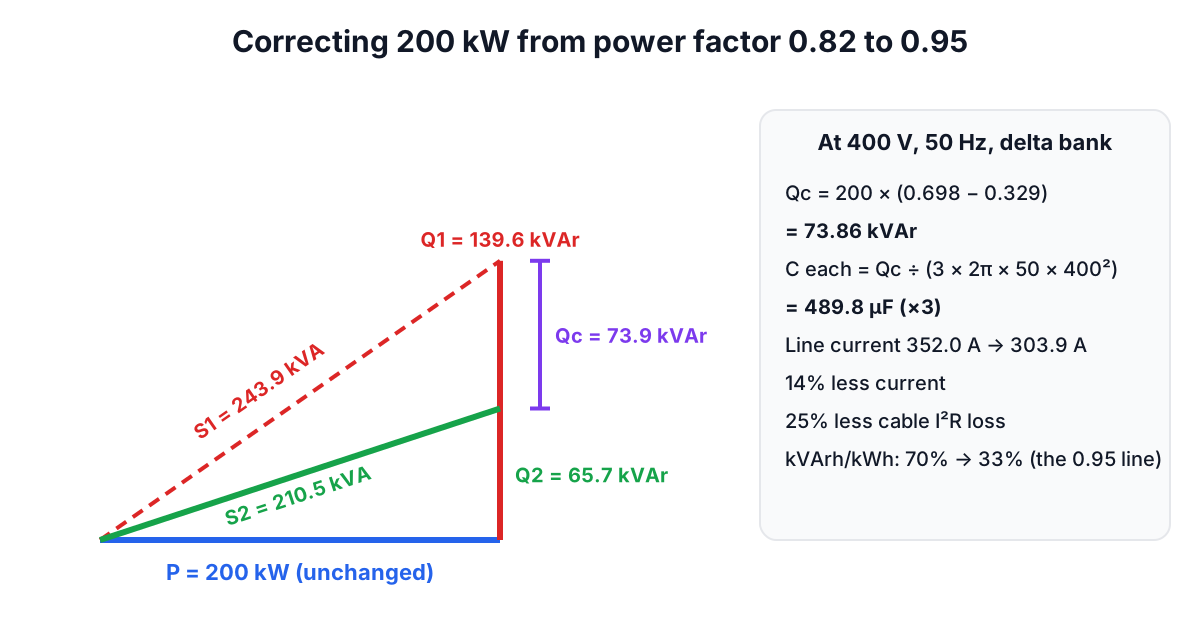
A factory unit drawing 200 kW at a power factor of 0.82 needs 73.86 kVAr of capacitors to reach 0.95. That bank cuts the current on each phase of a 400 V supply from 352.0 A to 303.9 A, frees about 33 kVA of capacity, and, on a half-hourly metered supply, can remove the excess reactive power charge from the distribution part of the bill. This edition works through the UK version of the problem: how DNO charging statements measure power factor, how to size the bank for 400 V and 50 Hz with the UK power factor correction calculator, and where plain capacitors cause trouble.
Power factor on a UK supply
Power factor is the share of the current that does useful work: PF = kW ÷ kVA = cos φ. Induction motors, compressors, older fluorescent lighting and lightly loaded transformers draw magnetising current that lags the voltage and delivers no energy, but still heats every cable and transformer it passes through.
Under regulation 27 of the Electricity Safety, Quality and Continuity Regulations 2002, a low-voltage supply in Great Britain is declared at 230 V between phase and neutral and 50 Hz, with the voltage allowed to run up to 10% above or 6% below and the frequency within 1%. Three-phase sites see 400 V between lines. Those two numbers, 400 V and 50 Hz, set the capacitance you need.
How the reactive charge is measured
On half-hourly metered business supplies, the distribution use-of-system (DUoS) charges in your DNO's charging statement can include a charge in pence per kVArh for excess reactive units. Western Power Distribution's East Midlands statement effective from 1 April 2012 shows how the rule was built: the charge applied when a site's reactive energy in kVArh exceeded 33% of its active energy in kWh in any half-hour, which it describes as equivalent to an average power factor of 0.95. Reactive units above that 33% were charged, calculated every half-hour and added up over the billing period. That statement is historical; the threshold, rate and method for your site are in your DNO's current statement, so read its reactive power clause before you build a business case.
The 33% figure is just tan φ at 0.95, which is 0.3287. At 0.82, tan φ is 0.698, so a site uses about 70 kVArh for every 100 kWh. Over a month of 44,000 kWh at that power factor, about 16,192 kVArh would sit above a 33% threshold. Multiply that by the pence per kVArh in your DNO's statement to see what the charge is worth.
Two details matter in practice. Because the test runs half-hour by half-hour, a good monthly average can still hide poor half-hours, for example at start-up or overnight when only compressors run. And Ofgem's 2016 decision on DCUSA change DCP222 stopped excess reactive power charges for generators under the common distribution charging methodology (CDCM) that their DNO asks to run below 0.95, so the rule is not the same for exporting sites.
Sizing the bank
A capacitor supplies leading reactive power that cancels part of the lagging reactive power. The real power stays the same, so the kVAr needed is:
Qc = P × (tan φ1 − tan φ2), φ = arccos PF
For the 200 kW site, tan(arccos 0.82) = 0.698 and tan(arccos 0.95) = 0.329, so Qc = 200 × 0.369 = 73.86 kVAr.
| Target | Bank | Line current at 400 V | kVA |
|---|---|---|---|
| None (0.82) | 0 | 352.0 A | 243.9 |
| 0.95 | 73.86 kVAr | 303.9 A | 210.5 |
| 0.97 | 89.48 kVAr | 297.6 A | 206.2 |
Going from 0.95 to 0.97 costs another 15.6 kVAr for 6 A less current. Unless your charging statement sets its threshold above 0.95, the extra steps pay back only through a little more capacity and lower cable losses.
Capacitance at 50 Hz
For a delta bank, each of three capacitors sits across the 400 V line voltage:
C (each) = Qc ÷ (3 × 2π × 50 × 400²) = 73,860 ÷ (3 × 314.16 × 160,000) = 489.8 µF
In star each capacitor sees 231 V and must be three times larger, 1,469.5 µF. A single 2.2 kW motor at 230 V and PF 0.75 needs 1.22 kVAr to reach 0.95, a 73.2 µF capacitor, and its current falls from 12.75 A to 10.07 A. Do not reuse a 60 Hz figure from an American catalogue: at 50 Hz the same kVAr needs a fifth more capacitance, and a 60 Hz figure would leave the bank about a sixth short.
Voltage rating
A capacitor's output falls with the square of the voltage across it. A unit rated 50 kVAr at 440 V gives only (400 ÷ 440)² = 82.6% of that, about 41 kVAr, on a 400 V bus. Rate the bank for the top of the supply tolerance as well: 230 V + 10% is 253 V phase, about 438 V between lines, before any harmonic voltage. Low-voltage self-healing capacitors are made to IEC 60831-1.
Capacity, not just charges
For some sites the bigger prize is headroom. Where your connection agreement sets a maximum import capacity in kVA, correction reduces the kVA drawn for the same kW: 243.9 kVA becomes 210.5 kVA in the example. If a new machine would otherwise take the site over its agreed capacity, correction can delay or avoid an application to the DNO for more. Whether a lower capacity also lowers your standing charges depends on your DNO's capacity charges.
Harmonics and detuned banks
Variable speed drives, LED drivers and UPS units draw harmonic currents. A plain capacitor bank and the supply transformer form a resonant circuit, and if its resonance lands near the 5th (250 Hz) or 7th (350 Hz) harmonic, the bank can amplify the harmonics, overheat and fail. Where non-linear loads are a large share of the site, designers fit detuned banks with series reactors; a 7% detuning puts the resonance at 50 ÷ √0.07 = 189 Hz, below the 5th harmonic. A harmonic survey before buying is cheaper than replacing a failed bank.
Where to fit it
- At the main switchboard, in automatic steps. A controller switches stages in and out to follow the load, which avoids a leading power factor at night or at weekends when the motors stop. This is the usual choice for a site with varied load.
- At large motors. The capacitor switches with the motor and cuts current in its own cable, but must stay below the motor's no-load magnetising kVAr or the motor can self-excite when switched off.
- Never aim for exactly 1.0 with a fixed bank: once load falls, the site goes leading, voltage rises and capacitors are stressed.
Capacitors hold their charge after isolation, so banks need discharge resistors and a wait before anyone works on them. A competent electrical contractor should design the bank with your half-hourly data in hand.
Frequently asked questions
What power factor triggers a reactive charge in the UK?
The trigger is set in your DNO's use-of-system charging statement. The WPD East Midlands statement from 2012 charged reactive units above 33% of active units in each half-hour, equivalent to an average power factor of 0.95; check the current statement for your area.
How many kVAr do I need to get from 0.82 to 0.95?
Multiply the kW by 0.369. For a 200 kW load that is 73.86 kVAr, or 489.8 µF per capacitor in a 400 V, 50 Hz delta bank.
Does power factor correction reduce my kWh?
Barely. The kWh the machines use stays the same; the savings are in reactive charges, capacity headroom and a small cut in cable losses, which fall by about 25% when the current drops from 352 A to 304 A.
Should I worry about harmonics before fitting capacitors?
Yes, if the site has many drives, UPS units or LED drivers. A plain bank can resonate with the supply transformer; a detuned bank with series reactors avoids it.
Sources and further reading
- The Electricity Safety, Quality and Continuity Regulations 2002, regulation 27, legislation.gov.uk. 230 V and 50 Hz declared supply with +10% / −6% and ±1% tolerances.
- Use of System Charging Statement, WPD East Midlands, effective 1 April 2012, National Grid Electricity Distribution (formerly WPD). Paragraph 2.37: the 33% kVArh to kWh half-hourly threshold, equivalent to 0.95. Historical example.
- DCUSA DCP222: non-billing of excess reactive power charges, Ofgem. Generators asked by their DNO to run below 0.95.
- Service and Installation Rules of NSW, Section 6, NSW Government. A published kVAr multiplier table (Table 6-1) to check the tan φ arithmetic against, and the IEC 60831-1 requirement.
- Reducing power factor cost, US Department of Energy. How capacitors cut reactive demand.
Open the Power Factor Correction Calculator
More Electrical
Every tool in the Electrical section, free and in your browser.