
Duct Sizing for Extract Fans and MVHR in the UK
How to size ventilation ducts in mm from flows in l/s: velocity and equal friction, Pa per metre, flat channel equivalents and the Approved Document F limits.
By Redbison Dev · · 10 min read

United Kingdom edition. Written for UK homes: flows in litres per second and ducts in millimetres, the Approved Document F extract and whole dwelling rates for England, the 2021 ducting rules in force now and the 2026 edition's 2 m and static pressure limits from 24 March 2027. US edition
In a UK home, duct sizing usually means one of two jobs: getting a bathroom, kitchen or utility extract fan to deliver its Approved Document F rate through the duct it is connected to, or laying out an MVHR network that stays quiet and inside the unit's fan curve. Both come down to the same physics. A 15 l/s bathroom fan in 100 mm rigid duct loses about 0.65 Pa per metre; in 100 mm flexible duct, 1.31 Pa per metre; and a 31 l/s MVHR trunk forced into 100 mm loses nearly three times as much per metre as one in 125 mm.
This edition works in litres per second, millimetres and pascals, quotes the England guidance with its paragraph numbers, and runs every figure through the UK duct size calculator. It explains the method; the installer and building control body decide what a particular house needs.
Start from the flow Approved Document F asks for
Approved Document F Volume 1 (2021 edition, the one in force in England now) sets the flows a duct has to carry:
| Room or system | Approved Document F 2021 | Flow |
|---|---|---|
| Kitchen, cooker hood extracting outside | Table 1.1, intermittent | 30 l/s |
| Kitchen, no extracting cooker hood | Table 1.1, intermittent | 60 l/s |
| Utility room | Table 1.1, intermittent | 30 l/s |
| Bathroom | Table 1.1, intermittent | 15 l/s |
| Sanitary accommodation (WC) | Table 1.1, intermittent | 6 l/s |
| Kitchen, continuous system high rate | Table 1.2 | 13 l/s |
| Bathroom or utility, continuous high rate | Table 1.2 | 8 l/s |
| Whole dwelling, 3 bedrooms | Table 1.3 | 31 l/s |
The whole dwelling rate is the higher of the bedroom figure (19 l/s for one bedroom, rising by 6 l/s per bedroom, 31 l/s for three) and 0.3 l/s per m² of internal floor area across all storeys. A 120 m² three-bedroom house needs 36 l/s, not 31, because the floor-area rule wins.
MVHR units are often rated in m³/h. Divide by 3.6 to get l/s: 112 m³/h is 31 l/s.
Method one: velocity, for a single fan
Continuity gives the diameter for a chosen air speed: D = √(4Q / πV). In SI units with Q in m³/s and V in m/s, D comes out in metres. For a 60 l/s kitchen extract at 4 m/s:
D = √(4 x 0.060 / (π x 4.0)) = 0.138 m = 138 mm, so 150 mm
In 150 mm the air runs at 3.40 m/s and loses 1.08 Pa/m. Fit the 125 mm spigot size instead and it runs at 4.89 m/s and 2.61 Pa/m, more than twice the friction, and the noise at the grille rises with it. Velocity is the right check for a single fan because noise is what people notice; it says nothing about whether the fan can push the flow, which is where friction comes in.
Method two: equal friction, for an MVHR network
Equal friction sizes every duct to the same pressure loss per metre; the calculator suggests 0.5 to 1 Pa/m as a starting range for house systems. The pressure loss in a round duct comes from the Darcy-Weisbach equation, with the friction factor from Colebrook:
Δp / L = (f / D) x ρV² / 2
1/√f = −2 log10( ε/(3.7 D) + 2.51/(Re √f) )
The calculator uses air at 1.204 kg/m³ (20 °C, sea level) and a roughness of 0.03 mm for smooth PVC or aluminium duct, 0.09 mm for galvanised steel and 3 mm for flexible duct pulled taut. It then rounds up to the 63, 80, 100, 125, 150, 160, 200 mm series.
For the 31 l/s three-bedroom MVHR trunk at 1 Pa/m in smooth duct:
| Duct | Speed | Friction |
|---|---|---|
| 100 mm | 3.95 m/s | 2.34 Pa/m |
| 125 mm (exact 119.4 mm) | 2.53 m/s | 0.80 Pa/m |
| 150 mm | 1.75 m/s | 0.34 Pa/m |
Branches are smaller. A kitchen extract branch at the 13 l/s continuous high rate needs only 86.6 mm at 1 Pa/m, so 100 mm, running at 1.66 m/s and 0.50 Pa/m. A bathroom at 8 l/s in 100 mm runs at 1.02 m/s and 0.22 Pa/m; dropping it to 75 mm raises that to 0.85 Pa/m.
Flat channel ducting: what it is equivalent to
Rectangular "flat channel" ducting fits between joists, but a rectangle does not carry the same air as a round duct of the same area: its corners add surface where the air slows. Huebscher's formula gives the round duct with the same friction:
De = 1.30 x (a x b)^0.625 / (a + b)^0.25
Applied to three flat channel sizes sold in the UK:
| Flat channel | Area | Equivalent round diameter | Friction at 30 l/s (smooth) |
|---|---|---|---|
| 110 x 54 mm | 5,940 mm² | 83.0 mm | 5.44 Pa/m |
| 204 x 60 mm | 12,240 mm² | 115.7 mm | 1.10 Pa/m |
| 220 x 90 mm | 19,800 mm² | 150.1 mm | 0.32 Pa/m |
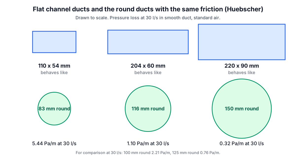
The 110 x 54 channel behaves like an 83 mm round duct, smaller than a 100 mm fan spigot; at 30 l/s it loses 5.44 Pa/m, five times what 204 x 60 loses at the same flow. And 204 x 60, at 116 mm equivalent, is a little below a 125 mm round (0.76 Pa/m at 30 l/s), so a 125 mm spigot reduced into it is a small step down, not a like-for-like swap.
The ducting rules: 2021 now, 2026 from 24 March 2027
Under the 2021 edition, paragraph 1.76 asks for rigid ducts wherever possible, and paragraph 1.77 allows flexible ductwork only for final connections, at most 1.5 m long, meeting BSRIA's BG 43/2013. Paragraph 1.79 asks for the shortest duct, fewest bends and appropriately sized ducts, and paragraph 1.80 for terminals with at least 90% of the duct's free area.
The 2026 edition of Volume 1 takes effect on 24 March 2027 for most work in England (24 September 2027 for higher-risk building work) and is much more specific:
- Fans: rigid ducting for intermittent extract fans, with a maximum length of 2.0 m where practical (paragraph 1.77). Longer runs need design calculations and drawings for building control showing the fan, ducting and terminal still achieve the flow (paragraph 1.78).
- Flexible duct: at most 200 mm, and only as a final connection to a fan spigot (paragraph 1.79). Where fans are controlled to a constant duct pressure, no flexible duct at all.
- Static pressure: Table 1.8 caps the design static pressure of the ductwork installation by total flow:
| Total flow | Continuous extract, several spigots | MVHR, or extract with one spigot |
|---|---|---|
| Up to 37 l/s | 30 Pa | 60 Pa |
| 38 to 53 l/s | 50 Pa | 110 Pa |
| 54 l/s and above | 80 Pa | 160 Pa |
- Insulation: at least the equivalent of 50 mm of material with conductivity of 0.04 W/m·K or less (vapour sealed) for intake and exhaust ducts in heated parts of the house, and 25 mm in lofts and sub-floor voids (paragraph 1.83).
- Testing: in existing homes, flow testing for new fans with more than 2 m of duct or more than one 90 degree offset (paragraph 4.26).
Checking a run against the 60 Pa budget
Take the 31 l/s MVHR system, under 37 l/s, so Table 1.8 allows 60 Pa. Its longest run is 12 m with six bends. Straight duct is friction times length; each bend costs its loss coefficient C times the velocity pressure ρV²/2. Bend coefficients come from manufacturers' data; C = 0.3 per bend is used here only to show the arithmetic.
| Trunk size | Straight 12 m | Six bends (C = 0.3) | Total |
|---|---|---|---|
| 125 mm at 2.53 m/s (velocity pressure 3.84 Pa) | 9.6 Pa | 6.9 Pa | 16.5 Pa |
| 100 mm at 3.95 m/s (velocity pressure 9.38 Pa) | 28.1 Pa | 16.9 Pa | 45.0 Pa |
The 125 mm trunk leaves most of the 60 Pa for the terminals, valves and the far branch; the 100 mm trunk has used three quarters of it before a single terminal is counted. That is the case for sizing the trunk by friction rather than by the size of the unit's spigots.
The bathroom fan through a loft
A 15 l/s bathroom fan with 100 mm spigots, ducted 3 m through the loft to a soffit vent:
- 100 mm rigid: 0.65 Pa/m, about 2.0 Pa of straight duct.
- 100 mm flexible: 1.31 Pa/m, about 3.9 Pa, before any sag.
- 125 mm rigid: 0.22 Pa/m, about 0.7 Pa.
Small axial fans lose flow quickly as back pressure rises, so these few pascals decide whether the fan delivers 15 l/s or something well short of it. From March 2027 a run over 2 m like this one, fitted as new work in an existing home, needs its flow tested and recorded.
Beyond the duct
- Leaks and joints: paragraph 1.81 (2021) wants connections mechanically secured and sealed, with rigid connectors and jubilee clips on flexible duct.
- Condensation: an uninsulated exhaust duct crossing a cold loft collects water that runs back to the fan.
- Outside the duct: the room flows feed the UK air changes calculator, and the UK edition of the air changes per hour guide covers how Approved Document F's rates compare. The fabric heat loss that MVHR recovers is in the UK heat loss calculator.
- Other UK nations: this edition quotes the documents for England; Scotland, Wales and Northern Ireland publish their own guidance, so check the rates and duct rules where the house is.
Frequently asked questions
Is 100 mm duct big enough for an MVHR system?
For branches, usually: 13 l/s in 100 mm smooth duct runs at 1.66 m/s and 0.50 Pa/m. For the main trunk of a three-bedroom house at 31 l/s, 100 mm runs at 3.95 m/s and 2.34 Pa/m, which uses up a 60 Pa budget quickly; 125 mm (0.80 Pa/m) or 150 mm (0.34 Pa/m) leaves room for terminals and bends.
What round duct is 204 x 60 flat channel equal to?
By Huebscher's formula, about 116 mm. It carries 30 l/s at 1.10 Pa/m, a little more friction than a 125 mm round duct at 0.76 Pa/m. The smaller 110 x 54 channel is equivalent to only 83 mm.
How long can an extractor fan duct be?
Under the 2021 edition in force now, use rigid duct wherever possible and keep any flexible section to a final connection of no more than 1.5 m. From 24 March 2027 the 2026 edition asks for rigid duct no longer than 2.0 m where practical, design calculations for longer runs, and flexible connections of no more than 200 mm.
How do I convert m³/h to l/s?
Divide by 3.6. An MVHR unit rated at 150 m³/h moves about 41.7 l/s; a fan rated at 54 m³/h moves 15 l/s. Check the fan curve at the pressure your ductwork creates, not the free-air figure.
Sources and further reading
- Approved Document F: Ventilation, Volume 1 Dwellings, 2021 edition, GOV.UK. Tables 1.1 to 1.3 and paragraphs 1.74 to 1.81 on installation and ducting.
- Approved Document F: Ventilation, Volume 1 Dwellings, 2026 edition, GOV.UK. Paragraphs 1.76 to 1.85, Table 1.8 and paragraph 4.26; takes effect on 24 March 2027.
- Approved Document F (2026), GOV.UK. Publication page and transitional arrangements.
- Ventilation: Approved Document F, GOV.UK. The edition in force and its amendments.
- Building regulations and approved documents index, GOV.UK. Where Approved Document F sits among the other parts.
- Turbulent flow in pipes (Colebrook, 1939), Journal of the Institution of Civil Engineers. The friction factor equation used by the calculator.
More HVAC & Plumbing
Every tool in the HVAC & Plumbing section, free and in your browser.