
Duct Sizing in Canada: Furnace Trunks, Fans and HRVs
How to size furnace trunks in cfm and inches and ventilation ducts in L/s and mm, with equal friction, flex duct and the NBC 2025 duct size tables.
By Redbison Dev · · 10 min read

Canada edition. Written for Canadian houses: forced-air trunks in cfm, inches and inches of water column as the trades work, and ventilation ducts in L/s and mm checked against National Building Code of Canada 2025 Tables 9.32.3.10.-A, 9.32.3.11.-A and 9.32.3.11.-B. US edition
In a house with forced-air heating, duct sizing starts at the furnace or heat pump blower: a heat loss calculation to CSA F280 picks the equipment, the equipment sets the airflow in cfm, and the trunk and runs are sized to carry it at a friction rate the blower can push. Ventilation fans are a second, smaller job in litres per second, and there the National Building Code of Canada 2025 gives its own duct size table. A 1,000 cfm trunk at 0.08 in.wg per 100 ft comes out at 15 in round or 18 x 10 in rectangular; a 25 L/s bathroom fan in 100 mm duct is allowed only about 2 m of run.
This edition works through both jobs, in the units each trade uses, with every calculation from the Canadian duct size calculator. It explains the method; a full design follows the HRAI and NBC references cited below, and provinces adopt the NBC with their own changes and dates, so check the code in force where you build.
Forced air: equal friction in cfm and inches
The equal-friction method sizes every duct to the same pressure loss per 100 ft, so the longest run sets the static pressure the blower must supply. Houses are commonly designed somewhere around 0.06 to 0.10 in.wg per 100 ft; the real figure comes from the blower's available external static pressure, minus the coil, filter and grilles, divided by the effective length of the longest run.
The calculator finds the friction from the Darcy-Weisbach equation with the Colebrook friction factor, at standard air (1.204 kg/m³) and a roughness of 0.09 mm for galvanized steel or 3 mm for flex duct pulled tight. For a 1,000 cfm blower:
| Friction rate | Exact round | Next round size | Velocity in that size | Friction in that size |
|---|---|---|---|---|
| 0.08 in.wg per 100 ft | 14.29 in | 15 in | 815 fpm | 0.063 |
| 0.10 in.wg per 100 ft | 13.65 in | 14 in | 935 fpm | 0.088 |
Trunks under a basement ceiling
A rectangular trunk lets you trade depth for width where a basement ceiling limits headroom. The calculator converts the round size to rectangles with the same friction using Huebscher's equivalent diameter, De = 1.30 (ab)^0.625 / (a + b)^0.25. At 1,000 cfm and 0.08:
| Trunk | Aspect ratio | Velocity | Friction per 100 ft |
|---|---|---|---|
| 18 x 10 in | 1.8 | 800 fpm | 0.074 |
| 23 x 8 in | 2.9 | 783 fpm | 0.079 |
| 34 x 6 in | 5.7 | 706 fpm | 0.078 |
The 8 in deep trunk needs 184 in² of cross-section against 180 in² for 18 x 10, and the 6 in deep one 204 in², with far more sheet metal around it. Flat trunks work, but each inch of depth you give up costs width, metal and some friction.
Branch runs: rigid or flex
A 100 cfm branch at 0.08 needs 6.05 in exact, so the calculator steps up to 7 in. In 6 in galvanized it runs at 509 fpm and 0.083 in.wg per 100 ft, a hair over the target. The same 100 cfm in 6 in flex is 0.161, roughly double, and that is for flex pulled tight; sagging or compressed flex is far worse. 7 in flex brings it back to 0.071.
Fittings cost as much as the duct
Each elbow, boot and takeoff costs its loss coefficient C times the velocity pressure, (V / 4,005)² in.wg with V in fpm. In the 14 in trunk at 935 fpm the velocity pressure is 0.055 in.wg, so a fitting with C = 0.3 costs about 0.016 in.wg, the same as 19 ft of straight trunk at 0.088 per 100 ft. Manuals express fittings as equivalent lengths for exactly this reason; add them before you compare the total with the blower's rated external static pressure.
Ventilation ducts: what the NBC sets
Subsection 9.32.3 of NBC 2025 covers mechanical ventilation in houses. It fixes the flows, the pressure fans are rated at, and, for smaller ducts, the duct size itself.
Flows. Table 9.32.3.3. sets the principal ventilation fan's normal operating exhaust capacity by bedrooms: 16 to 24 L/s for one bedroom, 22 to 32 L/s for three, 30 to 45 L/s for five. Article 9.32.3.7. adds a supplemental exhaust fan of at least 50 L/s in each kitchen and 25 L/s in each bathroom or water-closet room the principal fan does not draw from.
Fan ratings. Table 9.32.3.10.-A says at what external static pressure a fan's rated capacity must be measured: 100 Pa (0.4 in.wg) for fans with ducts on both sides, such as an HRV; 62 Pa (0.25 in.wg) for the principal fan in an exhaust-only system; 25 Pa (0.1 in.wg) for other required fans such as bathroom fans.
Duct sizes. Sentence 9.32.3.11.(9) lets you size ventilation ducts with Table 9.32.3.11.-A instead of a full design. It gives the maximum length of round duct for each diameter, airflow and fan static pressure. An extract for fans rated at 25 Pa:
| Round duct | 15 L/s | 25 L/s | 35 L/s | 50 L/s |
|---|---|---|---|---|
| 100 mm (4 in) | 6 m | 2 m | 1 m | 0 m |
| 125 mm (5 in) | 17 m | 6 m | 3 m | 1 m |
| 150 mm (6 in) | 42 m | 16 m | 8 m | 4 m |
| 175 mm (7 in) | 60 m | 34 m | 18 m | 9 m |
A fan rated at 50 Pa gets roughly three times the length: 25 L/s through 100 mm is allowed 6 m, through 125 mm 18 m.
Checking the NBC table against the friction maths
Run the 25 L/s bathroom fan through the calculator in smooth duct:
| Round duct | Velocity | Friction | Straight-duct loss over the NBC length |
|---|---|---|---|
| 100 mm, 2 m allowed | 3.18 m/s | 1.60 Pa/m | 3.2 Pa |
| 125 mm, 6 m allowed | 2.04 m/s | 0.55 Pa/m | 3.3 Pa |
| 150 mm, 16 m allowed | 1.41 m/s | 0.23 Pa/m | 3.7 Pa |
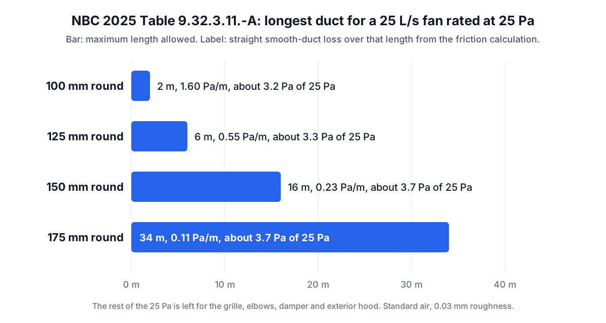
Each permitted length uses only about 3 to 4 Pa of the fan's 25 Pa on straight duct. The rest is left for the grille, elbows, the backdraft damper and the exterior hood, which on a small fan can easily cost more than the duct itself. That is why the table looks strict for 100 mm duct, and why one size up is the cheapest fix for a bathroom fan that does not clear the room.
The table's other rules:
- Flex duct (Sentence 9.32.3.11.(11)): pick the next larger diameter, or read the table for a duct twice as long as the real one. The calculator agrees: at 25 L/s, 125 mm flex loses 1.08 Pa/m, about double the 0.55 of smooth 125 mm.
- Rectangular duct (Table 9.32.3.11.-B): in place of 125 mm round, 125 x 100 mm at 100 mm depth, 100 x 125 mm at 125 mm depth, or a 75 x 250 mm stack duct. Above 175 mm, design to Subsection 9.33.4.
- Insulation (Sentence 9.32.3.11.(3)): an exhaust duct through an unheated space needs at least RSI 0.5, and an untempered outdoor air duct through heated space needs RSI 0.5 plus a vapour barrier.
- Joints and support: sealed with mastic, metal foil duct tape or the maker's sealant, and supported so the duct does not sag or crush.
The HRV and the kitchen fan
A three-bedroom principal fan at the top of its range, 32 L/s, through 125 mm galvanized duct runs at 2.61 m/s and 0.88 Pa/m; 150 mm drops that to 0.37 Pa/m. An HRV has ducts on both sides of its fans, so they are rated at 100 Pa, and Table 9.32.3.11.-A at 100 Pa allows 22 m of 125 mm duct and 53 m of 150 mm at 35 L/s, so most house runs fit at 125 mm or 150 mm.
The 50 L/s kitchen fan is the hard one. At a 25 Pa rating the table allows only 1 m of 125 mm duct and 4 m of 150 mm. Cooking appliance exhaust ducts must also be noncombustible and corrosion-resistant, run straight outdoors with no other connections, and have a grease filter at the intake (Sentence 9.32.3.11.(6)).
Before you finalize the layout
- Heat loss first. Article 9.33.5.1. sizes heating appliances to CSA F280; the ducts follow the equipment's airflow, not the other way round.
- Good practice references. Article 9.33.4.1. points heating and air-conditioning duct design to provincial rules or, failing those, good practice such as the ASHRAE Handbooks, the HRAI Digest and the SMACNA manuals; Article 9.32.3.2. adds the HRAI Residential Mechanical Ventilation Manual for ventilation.
- Returns. Article 9.33.6.13. asks for a return-air system designed to handle the entire air supply, and Article 9.33.6.12. for at least one return-air inlet on each floor level, with limited exceptions.
- Air changes. The Canadian air changes calculator turns the NBC fan rates into air changes per hour, explained in the Canadian edition of the air changes per hour guide, and the Canadian heat loss calculator gives the envelope losses behind the furnace size.
Frequently asked questions
What size trunk line do I need for 1,000 cfm?
At 0.08 in.wg per 100 ft in galvanized steel, 15 in round or about 18 x 10 in rectangular (800 fpm). At 0.10 the round drops to 14 in at 935 fpm. Use the friction rate your blower's available static pressure supports, after the filter, coil and fittings.
How long can a 4 inch bathroom fan duct be?
Under NBC 2025 Table 9.32.3.11.-A, a 25 L/s (53 cfm) fan rated at 25 Pa may use at most 2 m of 100 mm duct, or 6 m of 125 mm and 16 m of 150 mm. For flex, choose the next size up or read the table for twice the length.
Does flex duct need to be bigger than rigid duct?
Yes. Pulled tight, flex loses about twice as much per metre: 1.08 Pa/m against 0.55 Pa/m for 125 mm at 25 L/s. The NBC handles this by sending you to the next larger diameter or to the length column for a duct twice as long.
What static pressure are bathroom fans rated at in Canada?
NBC 2025 Table 9.32.3.10.-A asks for capacity measured at 25 Pa (0.1 in.wg) for required fans like bathroom fans, 62 Pa for the principal fan of an exhaust-only system and 100 Pa for fans with ducts on both sides, such as HRVs.
Sources and further reading
- National Building Code of Canada 2025, National Research Council Canada. Division B, Subsection 9.32.3 (Tables 9.32.3.3., 9.32.3.10.-A, 9.32.3.11.-A and -B) and Section 9.33.
- National Building Code of Canada 2025, catalogue record, Government of Canada Publications.
- Codes Canada, National Research Council Canada. The national model code editions.
- Turbulent flow in pipes (Colebrook, 1939), Journal of the Institution of Civil Engineers. The friction factor equation.
- Advanced Strategy Guideline: Air Distribution Basics and Duct Design, US Department of Energy. Friction rate and duct layout for forced-air houses.
More HVAC & Plumbing
Every tool in the HVAC & Plumbing section, free and in your browser.