
Three-Phase Power Formula UK: kW to Amps at 400 V
How P = √3 × 400 × I × PF works on a UK 230/400 V supply, why 415 V drawings give lower amps, motor kW plates, and per-phase loading on a TP&N board.
By Redbison Dev · · 10 min read

United Kingdom edition. Worked on the GB 230/400 V, 50 Hz supply declared under ESQCR regulation 27, with motors rated in kW, old 415/240 V drawings and BS 7671 named for the cabling step. US edition
On a British three-phase supply, a balanced load of 100 A per line at power factor 0.85 takes 58.9 kW: √3 × 400 V × 100 A × 0.85. Every symbol in that line is a choice. 400 V is the voltage between two lines, not the 230 V you measure at a socket. The 100 A is the current in each line, not the total. And 0.85 converts kVA, which heats the cables, into kW, which turns the meter. This edition works through those choices for UK supplies, with each figure reproducible in the UK three-phase power calculator.
What a UK supply actually delivers
Regulation 27 of the Electricity Safety, Quality and Continuity Regulations 2002 sets the declared low-voltage supply in Great Britain at 230 V, measured between phase and neutral at the supply terminals, and the frequency at 50 Hz. Unless the customer agrees otherwise in writing, the voltage may sit up to 10% above or 6% below 230 V, which is a band of 216.2 V to 253 V, and the frequency may move 1% either way.
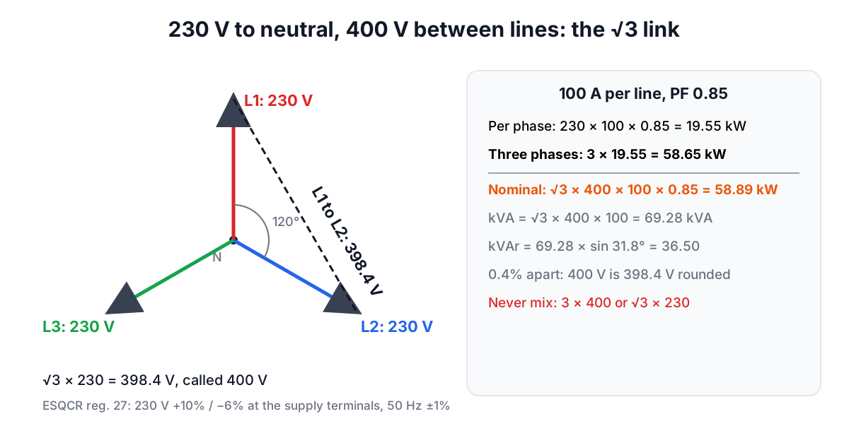
The three lines of a TP&N (triple pole and neutral) supply carry 230 V each to neutral, 120° apart. Between any two lines the voltage is 230 × √3 = 398.4 V, which is written as 400 V. Older drawings, switchgear and motor plates often say 415/240 V instead; that pair also differs by √3 (240 × 1.732 = 415.7). Neither is wrong, but mixing a 230 V neutral voltage with a 415 V line voltage on the same calculation is.
Two equivalent formulas, and the small gap between them
With a balanced load, each of the three phases supplies 230 × I × PF watts, so the total is 3 × 230 × I × PF. Because 230 V is the line voltage divided by √3, the same total can be written √3 × V(line) × I × PF. For the 100 A example:
| Route | Arithmetic | Result |
|---|---|---|
| Per phase, then × 3 | 3 × 230 × 100 × 0.85 | 58.65 kW |
| Line voltage with √3 | 1.732 × 400 × 100 × 0.85 | 58.89 kW |
| Apparent power | 1.732 × 400 × 100 | 69.28 kVA |
| Reactive power | 69.28 × sin(31.8°) | 36.50 kVAr |
The two kW figures differ by 0.4% only because 400 V is a rounded 398.4 V. That is well inside the legal voltage band, so either route is fine for design. The mistakes that matter are the large ones: 3 × 400 × I × PF overstates power by 73%, and √3 × 230 × I × PF understates it by 42%.
In the calculator, choose "3-phase line to line" with 400 V or "3-phase line to neutral" with 230 V. Both give the same kVA within that 0.4%.
Going from kW to amps
Most UK questions run the other way: a machine is rated in kW and you need the current per line to choose a protective device or check the supply. Divide instead of multiplying:
I (per line) = P ÷ (√3 × 400 × PF)
A 15 kW load at power factor 0.85 draws 15,000 ÷ (1.732 × 400 × 0.85) = 25.5 A in each line. Put the same 15 kW on one 230 V line and the current is 15,000 ÷ (230 × 0.85) = 76.7 A, three times as much on a single conductor. That ratio is why workshops, commercial kitchens and larger heat pumps are usually fed three-phase: the same power needs a third of the current in each conductor.
Motors: the kW on the plate is output
UK and European motors are rated in kW of shaft output. The supply has to provide that output plus the motor's losses, so efficiency goes in before the current is worked out:
I = (rated kW × 1000) ÷ (η × √3 × V × PF)
For a 7.5 kW motor with 90% efficiency and power factor 0.84 on 400 V, the input is 7.5 ÷ 0.90 = 8.33 kW, the apparent power is 8.33 ÷ 0.84 = 9.92 kVA, and the current is 14.3 A per line. Three versions of that motor show how sensitive the answer is:
| Assumption | Current per line |
|---|---|
| 400 V, η 90%, PF 0.84 | 14.32 A |
| Same motor, drawing marked 415 V | 13.80 A |
| Supply at the −6% limit, 376 V | 15.23 A |
| Plate kW typed in as input kW (efficiency forgotten) | 12.89 A |
The last row is an easy slip to make: it treats output as input and understates the current by 10%. In the calculator, pick "Motor rated output (kW)" so the efficiency is applied. The horsepower option is there for imported North American kit only.
Two cautions. The running current is not the starting current: a direct-on-line start draws several times more, and the protective device curve and any soft starter come from the maker's data, not this formula. And at light load both efficiency and power factor fall, so a 7.5 kW motor idling on a half-empty conveyor draws more current per useful kW than its plate suggests.
kW, kVA and kVAr on a UK bill and a UK board
- kVA is what the cables, switchgear and transformer carry, and the figure to compare with a supply or transformer rating.
- kW is what does the work and what the kWh meter integrates.
- kVAr is the magnetising current of motors and transformers. On business supplies it can attract a reactive power charge; the UK power factor correction guide shows how a capacitor bank is sized to cut it, and the power factor calculator does the arithmetic at 400 V and 50 Hz.
Unbalanced boards: work per phase
The √3 formula assumes the same current in all three lines. A distribution board that feeds mostly single-phase circuits rarely achieves that. Work each phase at 230 V instead, and let the heaviest phase decide.
Take a TP&N board with 9.2 kVA connected to L1, 6.9 kVA to L2 and 4.6 kVA to L3, all resistive. The phase currents are 40 A, 30 A and 20 A. Treating the 20.7 kVA total as balanced would suggest 29.9 A per line and hide the fact that L1 carries a third more than that. The neutral also carries the imbalance: for three resistive loads 120° apart it is √(40² + 30² + 20² − 40×30 − 30×20 − 20×40) = 17.3 A. Moving 2.3 kVA of circuits from L1 to L3 would bring all three phases to 30 A and the neutral current to zero.
A load connected between two lines, such as a 400 V welder, takes I = P ÷ (400 × PF) from those two lines and nothing from the third.
From current to cable
The current per line is the design current, Ib, which is where BS 7671 starts. The IET now lists BS 7671:2018+A4:2026 as the current edition of the Wiring Regulations, and says the transition period for Amendment 2 ended on 15 October 2026. Cable selection then depends on the installation method, grouping, ambient temperature, the protective device and voltage drop, none of which this formula covers. Have a qualified electrician design and certify the circuit; the HSE's guidance on safe working practices (HSG85) is aimed at anyone working on or near electrical equipment.
If the load is large enough to need its own transformer, the UK transformer sizing guide and the transformer calculator take the kVA from here and turn it into an IEC rating.
Frequently asked questions
Is UK three-phase 400 V or 415 V?
The declared supply is 230 V between phase and neutral (ESQCR regulation 27), so the line-to-line voltage is 230 × √3 = 398.4 V, written as 400 V. Older drawings and plates often still say 415/240 V. Use whichever pair your drawing uses, consistently; the current differs by about 4%.
How many amps does a 7.5 kW motor draw at 400 V?
About 14.3 A per line with 90% efficiency and power factor 0.84. Take both figures from the rating plate or data sheet: efficiency and power factor vary with size, speed and load, and the starting current is several times higher.
Why do I get a slightly different answer using 230 V and 3 instead of 400 V and √3?
Because 400 V is a rounded 398.4 V. With 100 A at power factor 0.85, 3 × 230 × 100 × 0.85 is 58.65 kW and √3 × 400 × 100 × 0.85 is 58.89 kW, a 0.4% difference that is far smaller than the permitted voltage variation.
How do I balance a three-phase distribution board?
Add up the load on each phase at 230 V and move circuits until the phase totals are close. A board with 40 A, 30 A and 20 A on its three phases carries 17.3 A in the neutral; moving 2.3 kVA from the heaviest to the lightest phase brings all three to 30 A.
Do I size the cable from kW or from amps?
From amps, the design current per line, which this formula gives you from kW, kVA or a motor rating. The cable size then follows BS 7671 and must be designed and certified by a qualified electrician.
Sources and further reading
- The Electricity Safety, Quality and Continuity Regulations 2002, regulation 27, legislation.gov.uk. Declared 230 V and 50 Hz, with +10% / −6% and ±1% permitted variations.
- BS 7671: Requirements for Electrical Installations, The Institution of Engineering and Technology. BS 7671:2018+A4:2026 as the current edition; Amendment 2 transition ended 15 October 2026.
- Electricity at work: Safe working practices (HSG85), Health and Safety Executive.
- IEC 60038: IEC standard voltages, International Electrotechnical Commission. The international series of standard nominal voltages.
- NIST Special Publication 811, National Institute of Standards and Technology. Appendix B unit conversion factors, for imported equipment rated in other units.
- The three-phase power formula (US edition), for 120/208 V and 277/480 V systems and NEC motor tables.
Open the Three-Phase Power Calculator
More Electrical
Every tool in the Electrical section, free and in your browser.