
Three Phase Power Formula: HP and kW to Amps at 415 V
Working out 3 phase current on India's 415 V, 240 V, 50 Hz supply: the √3 formula, HP motors, why voltage dips raise current, and keeping power factor at 0.95.
By Redbison Dev · · 10 min read

India edition. Built on the 415 V three phase and 240 V single phase, 50 Hz supply that BIS and the CPWD specifications describe, with motors in HP, CPWD's 0.95 power factor target and phase balancing at home. US edition
A 5 HP monoblock pump on a 415 V three phase supply, with 84% efficiency and power factor 0.82, draws about 7.5 A in each phase. The formula behind that number is P = √3 × V × I × PF, where V is the 415 V between two phases, I is the current in one phase and PF turns kVA into kW. This edition explains each part for Indian supplies, where pump and motor ratings are commonly quoted in HP and the voltage at the panel may differ from the nameplate's. Every figure can be checked in the three phase power calculator for India.
415 V and 240 V: one supply, two voltages
The Bureau of Indian Standards, in its summary of the IS 1180 transformer standards, gives the power supply for end users as 415 V, 3 phase (240 V, 1 phase), 50 Hz. The 240 V is what you measure from any phase (R, Y or B) to neutral. The 415 V is what you measure between two phases. They are linked by √3: 240 × 1.732 = 415.7 V.
Why √3? The three phase voltages are equal in size but displaced by 120°. The voltage between R and Y is the difference of two such phasors, and the geometry of a 120° triangle makes it 2 × sin 60° = √3 times longer than either one.
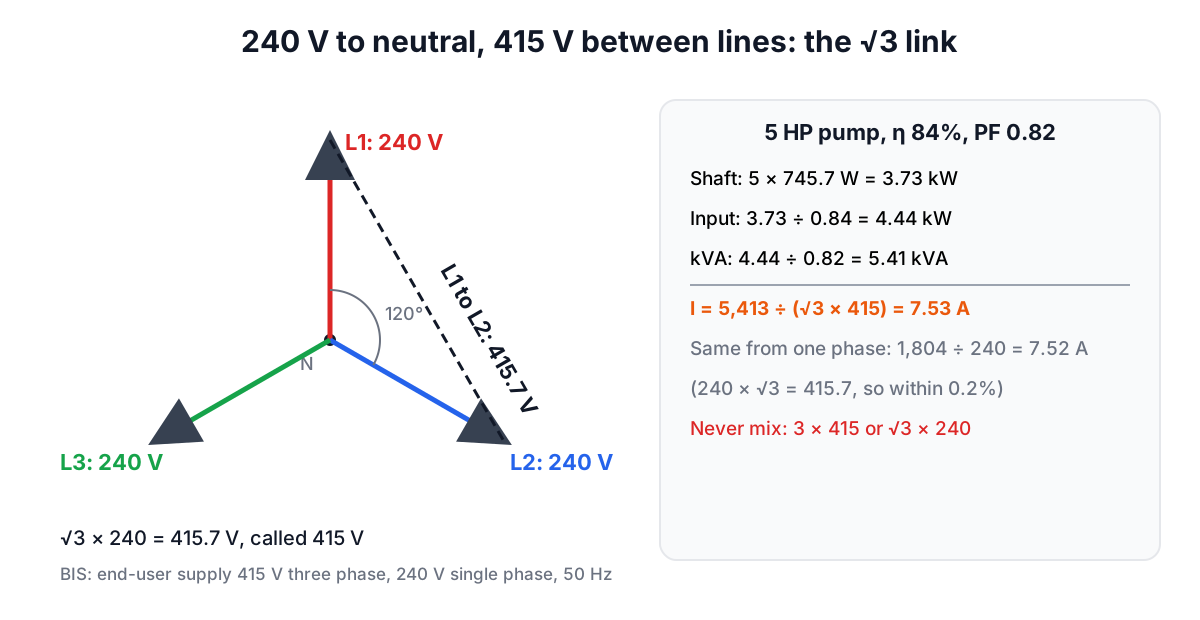
CPWD's General Specifications for Electrical Works write their switchboard requirements for a 415 V, 3 phase, 50 Hz, 4 wire system, so that is the voltage to use on Indian drawings. Imported equipment may say 400/230 V; enter whatever your drawing says, but do not mix 240 V with 415 V in one formula.
The two forms of the formula
Each phase of a balanced load delivers 240 × I × PF watts, so the total is 3 × 240 × I × PF. Writing 240 V as 415 ÷ √3 turns that into √3 × 415 × I × PF. They are the same formula:
| Form | Use it when | 100 A per phase at PF 0.85 |
|---|---|---|
| 3 × V(phase) × I × PF | You measured phase to neutral (240 V) | 61.20 kW |
| √3 × V(line) × I × PF | You measured between phases (415 V) | 61.10 kW |
| √3 × V(line) × I | You want kVA for a DG set or transformer | 71.88 kVA |
The 0.2% difference between the first two rows is only the rounding of 415.7 V to 415 V. The error to avoid is using 3 with 415 V, which overstates power by 73%, or √3 with 240 V, which understates it by 42%.
A useful shortcut on Indian panels: at 415 V, each ampere per phase is √3 × 415 ÷ 1,000 = 0.719 kVA. So 100 A per phase is about 72 kVA, which is the number to compare with a DG set or a sanctioned load in kVA.
HP to amps for motors
Nameplate HP is the shaft output. One horsepower is 745.7 W, and the supply has to provide that output plus the motor's losses:
I = (HP × 745.7) ÷ (η × √3 × 415 × PF)
For the 5 HP pump: output 3.73 kW, input 3.73 ÷ 0.84 = 4.44 kW, apparent power 4.44 ÷ 0.82 = 5.41 kVA, current 7.53 A per phase.
| Motor | Supply | η | PF | Current |
|---|---|---|---|---|
| 1 HP single phase | 240 V | 70% | 0.80 | 5.55 A |
| 5 HP pump | 415 V, 3 phase | 84% | 0.82 | 7.53 A |
| 10 HP motor | 415 V, 3 phase | 88% | 0.85 | 13.87 A |
| Same 10 HP motor | 380 V at the panel | 88% | 0.85 | 15.15 A |
The single phase 1 HP motor takes three quarters of the current of a three phase motor five times its size, because it has one conductor instead of three and lower efficiency. The last row is worth checking on site: a motor delivers the same shaft power when the voltage sags, so it pulls more current. At 380 V the 10 HP motor draws 9% more than at 415 V, which heats the winding and can trip an overload relay that was set for the nameplate current.
Use the motor's own efficiency and power factor from its nameplate or catalogue. Leaving them at 100% and 1.0 would understate the 5 HP pump's current by about 31%. Starting current is a separate check: a direct online start draws several times the running current, which is why starters and MCB curves come from the motor maker's data.
Why CPWD sets a power factor target
The same 100 kW of useful load draws very different currents depending on power factor:
| Power factor | kVA | Current at 415 V |
|---|---|---|
| 0.70 | 142.9 | 198.7 A |
| 0.95 | 105.3 | 146.4 A |
| 1.00 | 100.0 | 139.1 A |
CPWD's specifications ask power consumers to maintain a power factor of not less than 0.95 lagging at the point of connection, and call for automatic power factor correction (APFC) panels to hold it there. Their table gives the benefit of going from 0.7 to unity as a 30% cut in load current and a 51% cut in transformer losses, which matches the arithmetic above: 139.1 ÷ 198.7 = 0.70, and losses fall with the square of current. They also warn against overcorrecting into a leading power factor. The power factor correction guide for India and the power factor calculator size the capacitor bank in kVAr.
Balancing phases in a three phase home
A home or shop with a three phase connection usually still wires most of its loads single phase at 240 V. The √3 formula assumes equal current in R, Y and B; a house rarely manages that, so work each phase on its own.
Suppose the geysers and the kitchen sit on R (4.8 kW, 20 A), the air conditioners on Y (2.4 kW, 10 A) and lighting and fans on B (1.2 kW, 5 A). The balanced formula on the 8.4 kW total would suggest only 11.7 A per phase; R actually carries 20 A. The neutral carries the imbalance, which for three resistive loads is √(20² + 10² + 5² − 20×10 − 10×5 − 5×20) = 13.2 A, more than the average phase current. Moving one 2.4 kW circuit from R to B gives 10 A on R, 10 A on Y and 15 A on B, and the neutral current falls to 5 A. Rebalancing is done at the distribution board by a licensed electrician.
From current to cable, MCB and transformer
The current per phase is the starting point for cable and switchgear selection, using the cable maker's tables and IS 732 (the code of practice CPWD's specifications refer to), which add the installation method, grouping, ambient temperature and voltage drop. A licensed electrical contractor should do that design. If the load is large enough for its own distribution transformer, remember that BIS describes Indian distribution transformers as having a 433 V three phase (250 V single phase) secondary, slightly above 415 V, which leaves room for the drop under load; the transformer sizing guide for India and the IS 1180 transformer calculator take it from there.
Frequently asked questions
What is the formula for 3 phase current at 415 V?
I = P ÷ (√3 × 415 × PF), with P in watts. For a motor, use P = HP × 745.7 ÷ efficiency. A 5 HP pump at 84% efficiency and power factor 0.82 draws 7.53 A per phase.
Is Indian three phase supply 415 V or 400 V?
BIS gives the end-user supply as 415 V three phase and 240 V single phase at 50 Hz, and CPWD writes its specifications for a 415 V, 3 phase, 4 wire system. Imported equipment may be marked 400/230 V; calculate with the voltage on your drawing.
Why does my motor take more current when the voltage is low?
A motor tries to deliver the same shaft power, so if the voltage falls the current rises roughly in proportion. A 10 HP motor drawing 13.87 A at 415 V draws about 15.15 A at 380 V.
How do I convert amps to kVA on a 415 V supply?
Multiply the current per phase by 0.719. So 100 A per phase is about 71.9 kVA; at power factor 0.85 that is 61.1 kW.
How should I balance load across R, Y and B phases?
Add up the connected load on each phase at 240 V and move circuits until the totals are close. In the example, moving one 2.4 kW circuit cut the neutral current from 13.2 A to 5 A.
Sources and further reading
- Transformers: summary of Indian Standards (IS 1180 and others), Bureau of Indian Standards. End-user supply of 415 V, 3 phase (240 V, 1 phase), 50 Hz; 433 V distribution transformer secondaries.
- General Specifications for Electrical Works, Part I: Internal (2013), Central Public Works Department. Section 2.6 power factor management (0.95 lag, APFC panels, current and loss reduction table) and the 415 V, 3 phase, 4 wire system.
- NIST Special Publication 811, National Institute of Standards and Technology. Appendix B unit conversion factors.
- IEC 60038: IEC standard voltages, International Electrotechnical Commission.
- IEC 60076-1: Power transformers, General, International Electrotechnical Commission.
- The three-phase power formula (US edition), for 120/208 V and 277/480 V systems.
Open the Three-Phase Power Calculator
More Electrical
Every tool in the Electrical section, free and in your browser.